


( 30 / 42 )
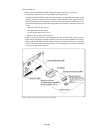
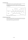
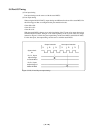
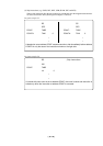
Figure 5.1 Waveform output from check pin TP5
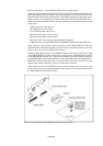
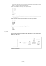
5.5 Pullup Transistor Control
Since ports P0 and P1 contain emulation circuits, you can not control the pullup resistors using the
pullup control register PU0. If you want to use the internal pullup resistors, turn on switches SW4 to
SW7 to activate the pullup resistors on the M34514T-MCU board.
The port's resistance value of the pullup resistor (RA1) is 68 kΩ.
5.4 Watchdog Timer
The M34514T-MCU does not have an operational watchdog timer. Therefore, use an evaluation
MCU (OTP version) to verify the operation associated with a watchdog timer.
The M34514T-MCU outputs a signal whose waveform is shown below from the check pin TP5
during WRST instruction execution cycles. This signal allows you to check the initialization cycle
of a watchdog timer.
WRST instruction
Next WRST instruction
System clock
XIN
WRST