


( 25 / 42 )
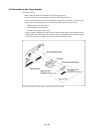
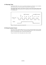
b. When Connecting to a 32-pin LQFP Foot Pattern on the Target System
Attach the pitch converter boards M34513T-PTCA and M34513T-PTCB to the 50-pin normal-
pitch cable (included with this product). Then connect the cable via the M34513T-PTCC to the
TQPACK032SA that has been soldered to the 32-pin LQFP foot pattern on the target system.
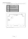
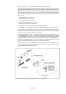
Figure 4.11 shows an example of how to connect to the target system using the M34513T-PTCA,
M34513T-PTCB, and M34513T-PTCC. Following products are required for connection to the
target system:
• 100-wire half-pitch cable (40 cm)
• PCA4029 pitch converter board
• 50-wire normal-pitch cable (10 cm)
• M34513T-PTCA pitch converter board
• M34513T-PTCB pitch converter board
• M34513T-PTCC pitch converter board (TQPACK* included)
* TQPACK consists of TQSOCKET032AF, TQSOCKET032SAP and TQPACK032SA.
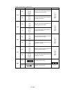
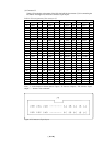
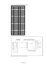
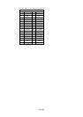
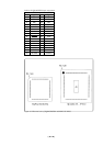
Table 4.10 shows the connector signal assignments of the TQPACK032SA. When the
TQPACK032SA and M34513T-PTCC are used for target system connection, the pin assign-
ments are the same as for the 32LQFP in 4513 Group.
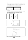
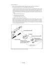
Solder the TQPACK032SA to the 32-pin LQFP foot pattern on the target system. The No. 1 pin
of the TQPACK032SA is located at its corner-cut part of package. Attach the M34513T-PTCC
to the TQPACK032SA with its No. 1 pin position (marked by a white dot) aligned with that of
the TQPACK032SA. After attaching the pitch converter boards M34513T-PTCA and M34513T-
PTCB to the 50-pin normal-pitch cable, connect the cable to the M34513T-PTCC. To avoid
damage to the emulator and target system, be careful of the connection.
When connecting cable and attaching the pitch converter boards, make sure the No. 1 pin
position of each connector is aligned with that of cable. Figure 4.12 shows the external view of
the TQPACK032SA and M34513T-PTCC.
Figure 4.11 Connecting to 32-pin LQFP foot pattern on target system