


( 20 / 42 )
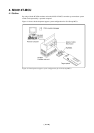
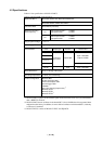
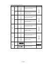
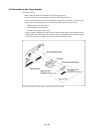
(2) Connector J4
To use the external trigger signal as event input of trigger breaks or trace points, connect the 2-
wire external trigger signal cable included with your M34514T-MCU board to the connector J4.
Connect the black clip of the external trigger cable to GND, and use the white clip for external
trigger signal input. Table 4.6 lists the pin assignments of the connector J4.
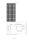
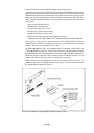
Table 4.6 Pin assignments of connector J4
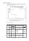
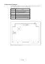
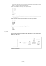
Figure 4.6 Pin layout of connector J6
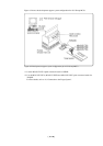
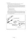
(3) Connector J6
The connector J6 is a connector used to connect an oscillator circuit board OSC-2. Table 4.7 lists
the pin assignments of the connector J6. Figure 4.6 shows the pin layout of the connector J6. For
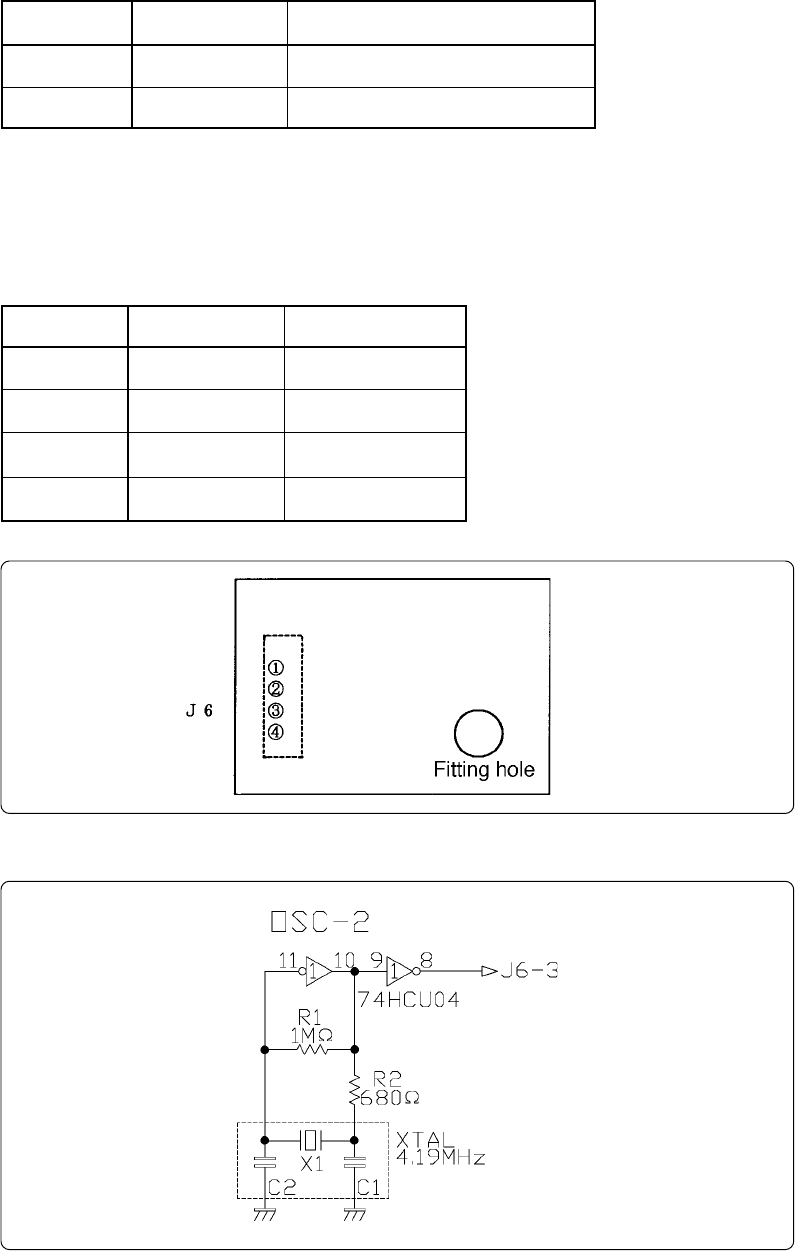
the 4.19 MHz operation with the oscillator circuit board OSC-2, see Figure 4.7.
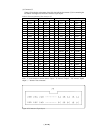
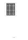
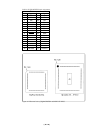
Table 4.7 Pin assignments of connector J6
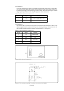
Figure 4.7 Circuit diagram of OSC-2 oscillator circuit board (4.19 MHz)
Pin No.
1
2
Signal
TRIG
GND
Function
External trigger signal input
GND input
Pin No.
1
2
3
4
Signal
VCC
GND
CLK
GND
Function
Power supply
GND
Clock input
GND