


( 27 / 42 )
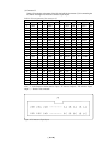
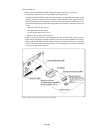
Some signals connected to the target system are emulated on the M34514T-MCU board. For
details, see "Chapter 6. Connection Circuit Diagram".
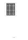
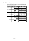
(1) Pins connected directly to the target system (8 types, 21 lines)
•P30 to P33
*1
•P40 to P43
*1
•P50 to P53
*1
•P20
•D6, D7
•AIN0 to AIN3
• VDCE
•VSS
*1 For 4513 Group MCUs, the ports P32, P33, P40 to P43 and P50 to P53 can not be connected to
the target system.
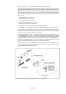
(2) Pins connected to the target system via emulation circuits etc. (6 types, 18 lines)
•P00 to P03
•P10 to P13
•P21 to P22
•D0 to D5
• RESET*
•VDD
(3) Pins not connected to the target system (3 types, 3 lines)
•XIN
•XOUT
• CNVSS
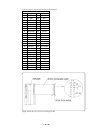
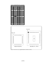
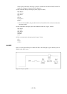
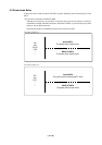
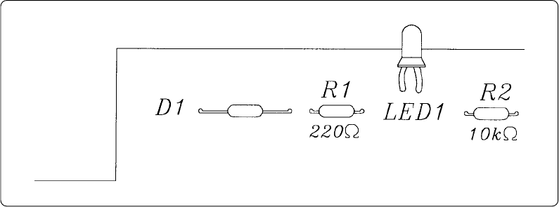
4.6 LED
Figure 4.13 shows the LED layout of M34514T-MCU. The LED lights in green when the power is
supplied to the MCU board.
Figure 4.13 Layout of LED