


( 29 / 42 )
5. Precautions to Be Taken When Debugging
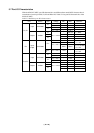
5.1 Reset
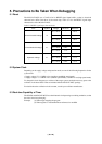
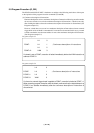
The M34514T-MCU uses a 74AC14 for its RESET signal input buffer, so that its electrical
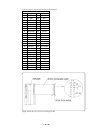
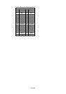
characteristics differ from those of the actual chip. Table 5.1 lists the RESET signal input
characteristics of the M34514T-MCU.
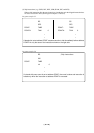
Table 5.1 RESET signal input characteristics
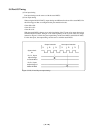
5.2 System Clock
Depending on the supply voltage and operation mode, use one of the following frequencies for the
system clock:
• Supply voltage 5 V: 4.2 MHz or less (medium-speed/high-speed mode)
• Supply voltage 3 V: 4.2 MHz or less (medium-speed mode), 2.0 MHz or less (high-speed mode)
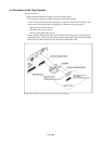
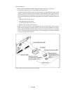
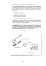
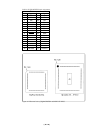
To change this clock frequency to suit that of the target system, attach the necessary parts to the
oscillator circuit board OSC-2 that are included with the M34514T-MCU package.
For details about the oscillation circuit constant, consult your oscillator manufacturer.
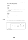
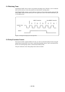
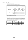
5.3 Real-time Capability of Timer
The PC4504 and M34514T-MCU have their internal clock operating even during emulation, so that
the timer values keep changing.
Example: (1) When single-stepping the program
(2) When registers or internal RAM are referenced or modified
H-level threshold voltage
L-level threshold voltage
Hysteresis voltage
Item Symbol
V
P
VN
VH
Voltage
VCC = 3.0 V
VCC = 4.5 V
VCC = 5.5 V
VCC = 3.0 V
VCC = 4.5 V
VCC = 5.5 V
VCC = 3.0 V
VCC = 4.5 V
VCC = 5.5 V
Maximum
2.2 V
3.2 V
3.9 V
-
-
-
1.2 V
1.4 V
1.6 V
Minimum
-
-
-
0.5 V
0.9 V
1.1 V
0.3 V
0.4 V
0.5 V