


( 37 / 42 )
6. Connection Circuit Diagram
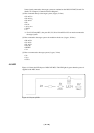
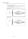
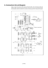
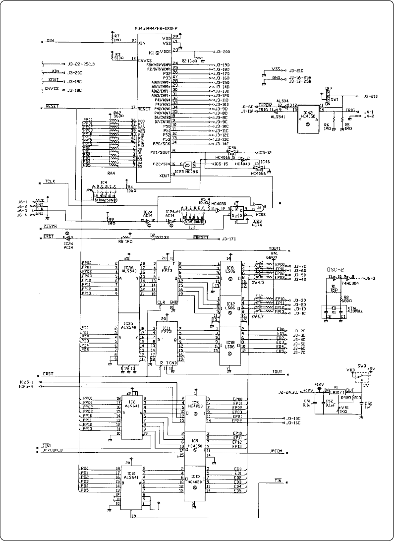
Figure 6.1 shows the connection circuit diagram of M34514T-MCU. This circuit diagram depicts the
M34514T-MCU connection centering on circuits connected to the target system. Emulator control
blocks and other similar circuits that are not connected to the target system are omitted in this diagram.
Figure 6.1 Connection circuit diagram
denotes control signal