


( 18 / 42 )
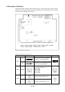
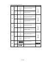
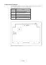
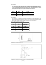
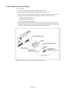
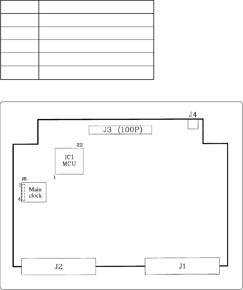
Figure 4.4 Positions of the connectors
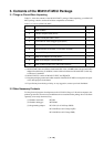
4.4 Description of Connectors
The M34514T-MCU board has five connectors. Table 4.4 lists the functions of these connectors.
Figure 4.4 shows the positions of connectors on the MCU board.
Table 4.4 Connectors
Connector
J1
J2
J3
J4
J6
Function
Connects the evaluation MCU bus.
Connects the monitor CPU bus.
Connects the target system. (100-pin)
Connects the external trigger signal. (2-pin)
Connects the oscillator circuit board. (4-pin)