


( 12 / 64 )
IMPORTANT
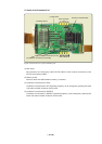
Note on Processor Mode Register (address D816):
• When using this product, the following precautions must be observed with the processor mode
register 0 in addition to those for the actual MCU.
(1) Software reset bit (bit 3)
If "1" is set for the software reset bit when the user program is not running, the MCU will be
reset while debug commands are being executed, thus commands will not end as they
normally do.
(2) Wait bit (bit 2)
With the emulator the areas affected by the wait bit differ from those of the actual MCU such
as mask ROM version or EPROM version MCUs.
(3) Processor mode bits (bit 1 and bit 0)
"00" is always read for the processor mode bits. To set the processor mode bits, be sure to set
"00". Setting other values can cause a malfunction.
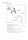
Notes on Target System:
•The Vcc pin is connected to the target system to observe the voltage of the target system. Therefore
the emulator cannot supply the power to the target system. Design your system so that the target
system is powered separately.
• The voltage of the target system should be within the MCU's specified range and between +2.6 and
5.5 V.
•Do not change the voltage of the target system after turning on the power.
• Before powering on your emulator system, check that the host machine, the PC4701, converter
board and target system are all connected correctly. Next, turn on the power to each equipment
following the procedure below.
(1) Turn ON/OFF the target system and the PC4701 as simultaneously as possible.
(2) When the PC4701 and emulator debugger M3T-PD77 start up, check the target status LEDs
on the emulator main unit's front panel to see if this product is ready to operate.
(For the target status LEDs on the emulator main unit's front panel when starting up the
PC4701, refer to "4.1 (3) LED Display When the PC4701 Starts Up Normally" on page 34.)