


Runco CL-610 Series Owner’s Operating Manual xi
1List of Figures
PRE
L
IMINAR
Y
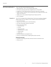
2-1. CL-610 Front/Side/Top View........................................................................................5
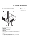
2-2. CL-610 Rear/Bottom/Side View ...................................................................................6
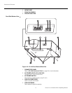
2-3. CL-610 Lens Controls and Status Indicators ................................................................7
2-4. CL-610 Connector Panel..............................................................................................8
2-5. CL-610 Remote Control.............................................................................................10
3-1. Estimating Throw Distance .........................................................................................16
3-2. Projector Placement...................................................................................................17
3-3. Folded Optics.............................................................................................................17
3-4. HDMI/DVI Source Connections ..................................................................................19
3-5. RGB Connections ......................................................................................................20
3-6. Progressive Component Video Connections...............................................................21
3-7. Composite, S-Video and Component Video Connections...........................................22
3-8. RS-232 Control System Connection...........................................................................23
3-9. Connecting the 12-Volt Trigger Output to Other Equipment........................................24
3-10. Anamorphic Lens Mounting Assembly - Exploded View ...........................................26
4-1. CL-610 OSD Menu Structure .....................................................................................31
4-2. Typical PLUGE Pattern for Adjusting Brightness.........................................................33
4-3. Typical Gray Bar Pattern for Adjusting Contrast..........................................................34
4-4. Typical Color Bar Pattern for Adjusting Color Saturation and Tint................................34
4-5. Typical Test Pattern for Adjusting Sharpness..............................................................36
7-1. CL-610 Dimensions....................................................................................................59