


Installation
38 Runco SC-1 Owner’s Operating Manual
PRE
L
IMINAR
Y
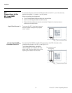
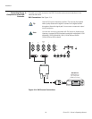
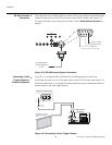
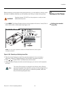
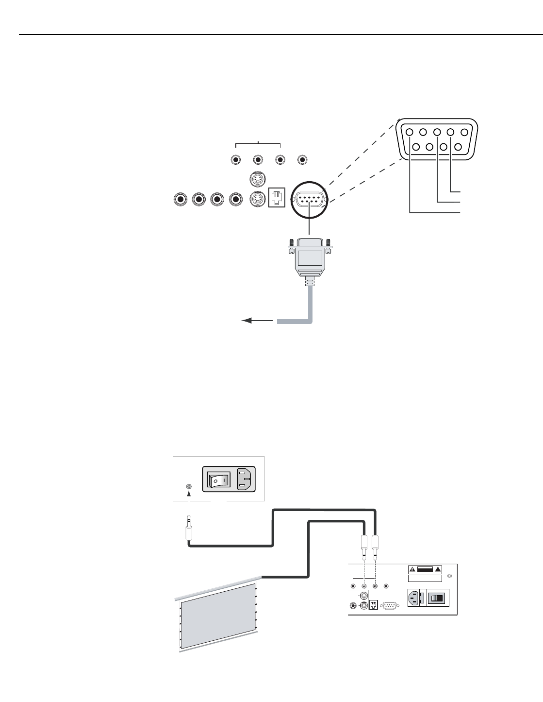
RS-232 Controller
Connection
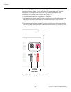
Use a standard, 9-pin RS-232 cable to connect a PC or home theater control/automation
system (if present) to the RS-232 Control port on the DHD Controller; see
Figure 3-18.
For more information about using this connection, refer to Serial Communications on
page 97.
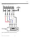
Figure 3-18. RS-232 Control System Connection
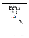
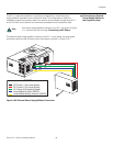
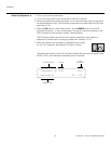
Connecting 12-Volt
Trigger Outputs to
External
Equipment
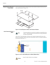
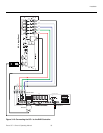
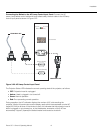
If your SC-1 is equipped with a CineWide with AutoScope system, connect the
AutoScope lens motor to a 12-volt trigger output on the DHD Controller; see
Figure 3-19.
Similarly connect other 12-volt trigger-activated equipment (such as retractable screens or
screen masks) to the other trigger outputs.
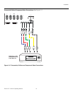
Figure 3-19. Connecting 12-Volt Trigger Outputs
➤
Pb Pr Y
Video
3
IR
RS-232 Control
S-Video 1
S-Video 2
1
2
TRIGGERS
RS-232 OutComponent Video
1
2
345
7
89
6
to Automation/
Control System
or PC
2 Transmit Data
3 Receive Data
5 Ground
(none of the other pins are used)
➤
Pb Pr Y
Video
3
IR
RS-232 Control
S-Video 1
S-Video 2
HD1
HD2
1
2
R/Pr G/Y B/Pb
R/Pr G/Y B/Pb H V
DVI 1 DVI 2DVI OutH/VVH
R/Pr G/Y B/Pb
HV
TRIGGERS
RS-232 Out
CAUTION:
TO REDUCE THE RISK OF ELECTRIC
SHOCK, DO NOT REMOVE COVER. NO USER-
SERVICEABLE PARTS INSIDE. REFER SERVICING
TO QUALIFIED SERVICE CENTER.
AVIS : RISQUE DE CHOC ELECTRIQUE-NE PAS OUVRIR
CAUTION
RISK OF ELECTRIC SHOCK
DO NOT OPEN
!
WARNING:
TO REDUCE THE RISK OF FIRE
OR ELECTRIC SHOCK, DO NOT EXPOSE
THIS APPLIANCE TO RAIN OR MOISTURE.
100-230VAC 50-60 Hz, 165 Watts Max
OUTPUTS
INPUTS
SYSTEM CONTROL INTERFACE
Component Video
SDI
Option
Serial No
Video Processor / Controller
Model
Runco International
Union City, CA
Made In USA
DHD Controller
Rear Panel
AutoScope Lens Motor (Rear)
3.5-mm
mini plug
AC Input
Power
Switch
Retractable Screen or other
12-Volt trigger-activated
device