


Maintenance and Troubleshooting
84 Runco SC-1 Owner’s Operating Manual
PRE
L
IMINAR
Y
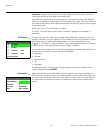
5.2
Maintaining Proper
Cooling
The high-intensity lamp and electronics rely on a variety of cooling components to reduce
internal operating temperatures. Regular checking and maintenance of the entire cooling
system is critical to prevent overheating and sudden projector failure, and helps to ensure
reliable operation of all projector components over time.
Ventilation Vents and louvers in the projector covers provide ventilation, both for intake
and exhaust. Never block or cover these openings. Do not install the projector
near a radiator or heat register, or within an enclosure.
Air Filter It is recommended that you replace the air filter (located on the lamp side of the projection
head) whenever you replace the lamp, or more often in dusty or dirty environments. A
clogged filter reduces air flow, and can lead to overheating and projector failure. Check
the air filter monthly. For detailed instructions, refer to
Lamp and Filter Replacement on
page 87. It is also recommended that you visually check the laminar airflow device (LAD)
located nearby. The LAD should be nearly white or light grey in color.
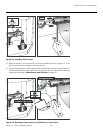
Liquid Cooler The liquid cooler system circulates liquid to and from the DMDs in the projection head,
reducing their operating temperature to an acceptable level. Periodically check the coolant
level visible by removing the igniter grille (rear side grille adjacent to the side input panel).
The reservoir should be approximately half-full.
FILLING THE COOLER: The cooler should require filling only upon projector installation.
Fill with a 50/50 mix of distilled water and ethylene glycol. Top off as necessary. Do not
overfill.
Exhaust Duct and Lamp
Fan Interlocks
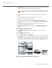
After installation, check and maintain operation of both vane switches — one in the
exhaust duct and one near the lamp fan — as follows:
1. Turn the projector on (lamp is not needed).
2. Turn your extractor fan OFF.
3. Confirm that the LCD status display shows that the extractor fan vane switch has
failed. Turn fan back ON to correct.
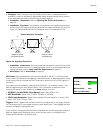
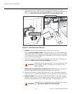
4. Block the air intake at the rear corner of the projection head (input side, next to the
ballast control and safety interlock connectors; see
Figure 2-1).
5. Confirm that the LCD status display shows that the lamp fan vane switch has failed.
Clear air intake to correct.
6. Repeat this procedure every six months in permanent installations.
Maintain vane switches as described in the next section, Maintenance and Cleaning.
➤
➤
➤
A failure of the liquid cooling system will trigger an over-temperature
alarm condition, clearly indicated with status displays at the top of
the projector.
Whenever coolant has been added or replaced, check for a
possible airlock upon the next projector power-up.
Note
WARNING
➤