


DISK DRIVE OPERATION
SpinPoint V40 Product Manual
98
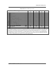
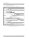
Table 6-19 Ultra DMA data burst timing requirements (cont).
NOTES −
1 Timing parameters shall be measured at the connector of the sender or receiver to which the parameter applies. For example,
the sender shall stop generating STROBE edges t
RFS
after the negation of DMARDY-. Both STROBE and DMARDY- timing
measurements are taken at the connector of the sender.
2 All timing measurement-switching points (low to high and high to low) shall be taken at 1.5V.
3 t
UI
, t
MLI
, and t
LI
indicate sender-to-recipient or recipient-to-sender interlocks, i.e., either sender or recipient is waiting for the
other to respond with a signal before proceeding. t
UI
is an unlimited interlock that has no maximum time value. t
MLI
is a
limited time-out that has a defined minimum. t
LI
is a limited time-out that has a defined maximum.
4 The test load for t
DVS
and t
DVH
shall be a lumped capacitor load with no cable or receivers. Timing for t
DVS
and t
DVH
shall be
met for all capacitive loads from 15 to 40 pf where all signals have the same capacitive load value.
5 t
ZIORDY
may be greater than t
ENV
since the device has a pull up on IORDY- giving it a known state when released.
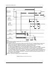
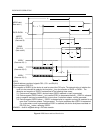
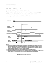
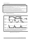
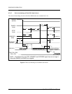
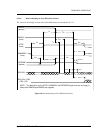
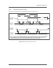
6.7.4.3 Sustained Ultra DMA data in burst
The values for the timings for each of the Ultra DMA modes are contained in 6.7.4.2.
t
DVH
DSTROBE
at device
DD(15:0)
at device
DSTROBE
at host
DD(15:0)
at host
t
DVH
t
CYC
t
CYC
t
DVS
t
DVS
t
DH
t
DS
t
DH
t
DS
t
2CYC
t
DH
t
DVH
t
2CYC
NOTE − DD(15:0) and DSTROBE signals are shown at both the host and the device to emphasize
that cable settling time as well as cable propagation delay shall not allow the data signals to be
considered stable at the host until some time after they are driven by the device.
Figure 6-5 Sustained Ultra DMA data in burst