


DISK DRIVE OPERATION
SpinPoint V40 Product Manual
42
6.2.3.12 IORDY (I/O Channel Ready)
This signal is active low to extend the host transfer cycle of any host register access (Read or Write) when the
drive is not ready to respond to a data transfer request. When IORDY is not negated, this signal is in the high
impedance state.
6.2.3.13 PDIAG- (Passed Diagnostics)
This signal is asserted by Drive 1 to indicate to Drive 0 that it has completed diagnostics. A 10K pull-up
resistor is used on this signal by each drive.
Following a power-on reset, software reset, or RESET-, Drive 1 negates PDIAG- within 1 msec (to indicate
to Drive 0 that it is busy). Drive 1 then asserts PDIAG- within 30 seconds to indicate that it is no longer busy
and is able to provide status. After the assertion of PDIAG-, Drive 1 will be unable to accept commands until
it has finished its reset procedure and is Ready (DRDY=1).
Following the receipt of a valid Execute Drive Diagnostics command, Drive 1 negates PDIAG- within 1
msec to indicate to Drive 0 that it is busy and has not yet passed its drive diagnostics. If Drive 1 is present,
then Drive 0 waits for up to 5 seconds from the receipt of a valid Execute Drive Diagnostics command for
Drive 1 to assert PDIAG-. Drive 1 clears BSY before asserting PDIAG-, as PDIAG- is used to indicate that
Drive 1 has passed its diagnostics and is ready to post status.
If DASP- was not asserted by Drive 1 during reset initialization, Drive 0 posts its own status immediately
after it completes diagnostics, and clears the Drive 1 Status register to 00h. Drive 0 will be unable to accept
commands until it has finished its reset procedure and is Ready (DRDY=1).
6.2.3.14 RESET- (Drive Reset)
This signal is asserted from the host system to reset the drive. It shall be asserted for at least 25 µsec after
voltage levels have stabilized during power-on; it is negated thereafter unless some event requires that the
drive(s) be reset following power-on.
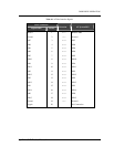
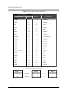
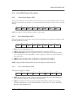
Table 6-1 shows the correlation between the signals at the ATA interface and the host AT bus.