


DISK DRIVE OPERATION
SpinPoint V40 Product Manual
48
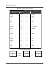
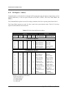
6.3.2 I/O Register - Address
Communication to or from the drive is through an I/O register that routes the input or output data to or from
registers addressed by a code on signals from the host (CS1FX-, CS3FX-, DA2, DA1, DA0, DIOR- and
DIOW-).
The Command Block registers are used for sending commands to the drive or posting status from the drive.
The Control Block registers are used for drive control and to post-alternate status. Table 6-3 lists these
registers and the addresses that select them.
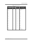
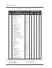
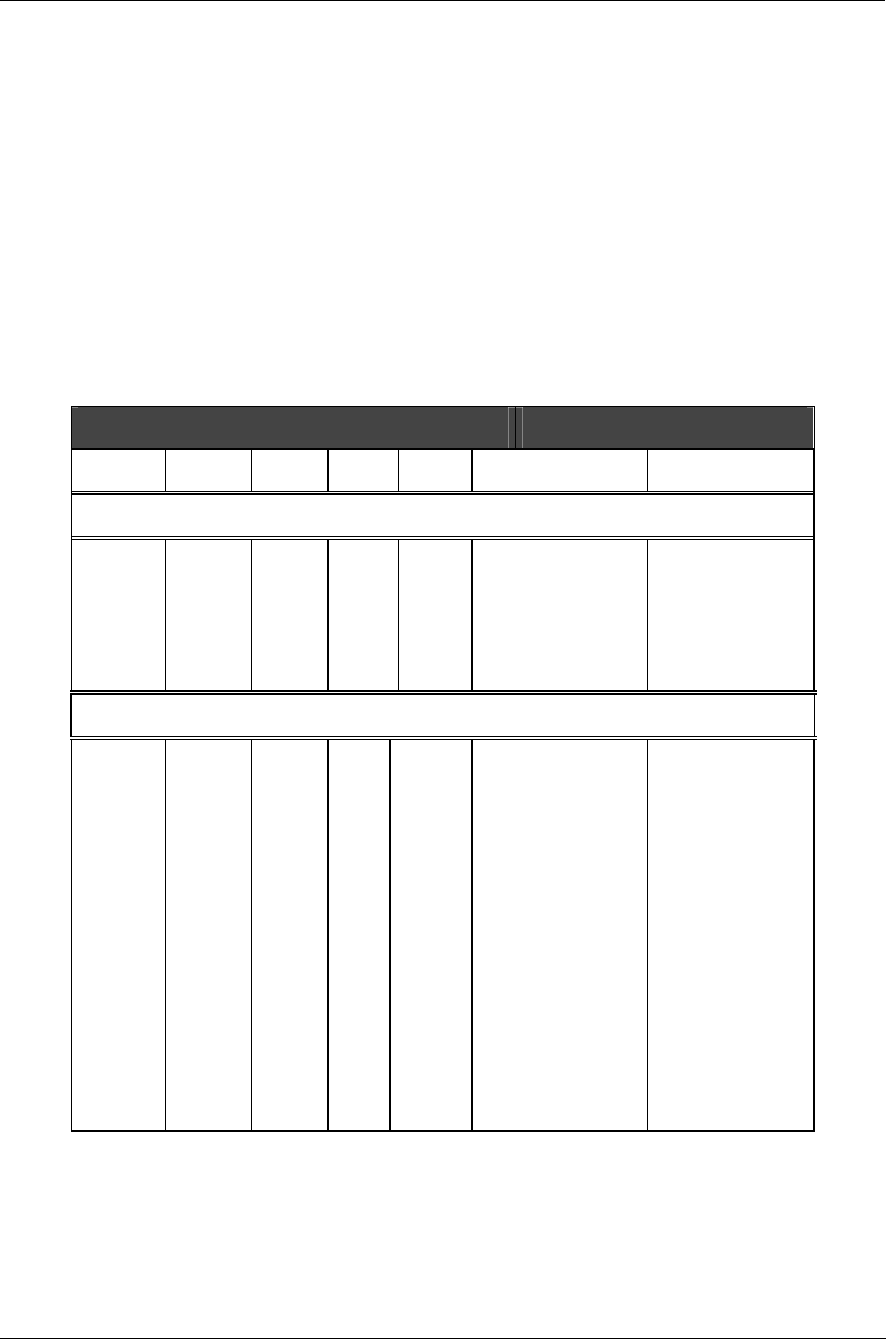
Table 6-3 I/O Port Function/Selection Address
Address Functions
CS1FX- CS3FX- DA2 DA1 DA0 READ(DIOR-) WRITE(DIOW-)
Control Block Registers
N N X X X High Impedance Not Used
N A 0 X X High Impedance Not Used
N A 1 0 X High Impedance Not Used
N A 1 1 0 Alternate Status Device Control
N A 1 1 1 Device Address Not Used
Command Block Registers
A N 0 0 0 Data Data
A N 0 0 1 Error Register Features
A N 0 1 0 Sector Count Sector Count
A N 0 1 1 Sector Number Sector Number
A N 0 1 1 * LBA bits 0-7 * LBA bits 0-7
A N 1 0 0 Cylinder Low Cylinder Low
A N 1 0 0 * LBA bits 8-15 * LBA bits 8-15
A N 1 0 1 Cylinder High Cylinder High
A N 1 0 1 * LBA bits 16-23 * LBA bits 16-23
A N 1 1 0 Drive/Head Drive/Head
A N 1 1 0 * LBA bits 24-27 * LBA bits 24-27
A N 1 1 1 Status Command
N N X X X Invalid Address Invalid Address
* Mapping of registers in LBA mode.
Logic conventions are:
A = signal asserted
N = signal negated
X = don't care