


DISK DRIVE OPERATION
SpinPoint V40 Product Manual
46
6.3 Logical Interface
6.3.1 General
6.3.1.1 Bit Conventions
Bit names are shown in all upper case letters except where a lower case n precedes a bit name. This indicates
that when nBIT=0 (bit is zero) the action is true, and when nBIT=1 (bit is one) the action is false. If there is
no proceeding n, then when BIT=1 it is true, and when BIT=0 it is false.
A bit can be set to one or cleared to zero, and polarity influences whether it is to be interpreted as true or
false:
True BIT=1 nBIT=0
False BIT=0 nBIT=1
6.3.1.2 Environment
Data is transferred in parallel (16 bits) either to or from host memory to the device’s buffer under the
direction of commands previously transferred from the host. The device performs all of the operations
necessary to properly write data to, or read data from, the media. Data read from the media is stored in the
device’s buffer pending transfer to the host memory, and data is transferred from the host memory to the
device’s buffer to be written to the media.
The devices using this interface shall be programmed by the host computer to perform commands and return
status to the host at command completion. When two devices are daisy chained on the interface, commands
are written in parallel to both devices, and for all except the Execute Diagnostics command, only the selected
device executes the command. On an Execute Diagnostics command addressed to Device 0, both devices
shall execute the command, and Device 1 shall post its status to Device 0 via PDIAG-.
Drives are selected by the DEV bit in the Drive/Head register (see 6.3.4.9), and by a jumper or switch on the
device designating it as either Device 0 or Device 1. When DEV=0, Device 0 is selected. When DEV=1,
Device 1 is selected. When a single device is attached to the interface, it shall be set as Device 0.
Throughout this document, device selection always refers to the state of the DEV bit, the position of the
Device 0/Device 1 jumper or switch, or use of the CSEL pin.
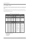
A device can operate in either of two addressing modes, CHS or LBA, on a command-by-command basis. A
device, which can support LBA mode, is indicated in the register, Sector Number register, Cylinder Low
mode in the Device/Head register, Sector Number register, Cylinder Low register, Cylinder High register and
HS3-HS0 of the Device/Head register contains the zero based-LBA.
This term defines the addressing mode of the device as being by physical sector address. The physical sector
address is made up of three fields: the sector number, the head number and the cylinder number. Sectors are
numbered from 1 to a device specific maximum value, which cannot exceed 255. Heads are numbered from 0
to a device specific maximum value, which cannot exceed 15. Cylinders are numbered from 0 to a device
specific maximum value, which cannot exceed 65,535. Typically, sequential access to the media is
accomplished by treating the sector number as the least significant portion, the head number as the mid
portion, and the cylinder number as the most significant portion of the CHS address.