


DISK DRIVE OPERATION
SpinPoint V40 Product Manual
49
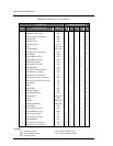
6.3.3 Control Block Register Descriptions
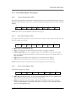
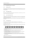
6.3.3.1 Alternate Status Register (3F6h)
This register contains the same information as the Status register in the Command Block register. The only
difference is that reading this register does not imply interrupt acknowledgment nor does it clear a pending
interrupt.
7 6 5 4 3 2 1 0
BSY DRDY DWF BSY DRQ CORR IDX ERR
NOTE: See section 6.3.4.10 for definitions of the bits in this register.
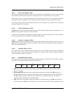
6.3.3.2 Drive Address Register (3F7h)
This register contains the inverted drive select and head select addresses of the currently selected drive. The
bits in this register are as follows:
7 6 5 4 3 2 1 0
HiZ nWTG nHS3 nHS2 nHS1 nHS0 nDS1 nDS0
• HiZ is always in a high impedance state.
• nWTG is the Write Gate bit. When writing to the disk drive is in progress, nWTG=0.
• nHS3 through nHS0 are the one's complement of the binary coded address of the currently selected
head. For example, if nHS3 through nHS0 are 1100b, respectively, then head 3 is selected. nHS3 is the
most significant bit.
• nDS1 is the drive select bit for drive 1. When drive 1 is selected and active, nDS1=0.
• nDS0 is the drive select bit for drive 0. When drive 0 is selected and active, nDS0=0.
NOTE: Caching, translation and master/slave may cause this register to contain invalid data.
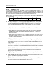
6.3.3.3 Device Control Register (3F6h)
The bits in this register are as follows:
7 6 5 4 3 2 1 0
X X X X 1 SRST nIEN 0
• SRST is the host software reset bit. The drive is held reset when this bit is set. If two disk drives are
daisy chained on the interface, this bit resets both simultaneously.
• nIEN is the enable bit for the drive interrupt to the host. When nIEN=0, and the drive is selected,
INTRQ is enabled through a tri-state buffer. When nIEN=1, or the drive is not selected, the INTRQ
signal is in a high impedance state.