


DISK DRIVE OPERATION
SpinPoint V40 Product Manual
51
6.3.4.5 Sector Count Register (1F2h)
This register contains the number of sectors of data requested to be transferred on a read or write operation
between the host and the drive. If the value in this register is zero, a count of 256 sectors is specified.
If this register is zero at command completion, the command was successful. If not successfully completed,
the register contains the number of sectors, which need to be transferred in order to complete the request.
The contents of this register may be defined otherwise on some commands (e.g., Initialize Drive Parameters
command, Format Track command).
6.3.4.6 Cylinder High Register (1F5h)
In CHS mode this register contains the high order bits of the starting cylinder address for any disk access. In
LBA mode this register contains bits 16-23 of the LBA.
At the end of the command, this register is updated to reflect the current disk address. The most significant
bits of the cylinder address are loaded into the Cylinder High register.
6.3.4.7 Cylinder Low Register (1F4h)
In CHS mode this register contains the low order 8 bits of the starting cylinder address for any disk access. In
LBA mode this register contains bits 8-15 of the LBA. At the end of the command, this register is updated to
reflect the current disk address.
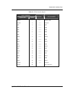
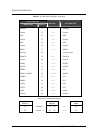
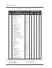
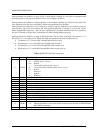
6.3.4.8 Command Register (1F7h)
This register contains the command code being sent to the drive. Command execution begins immediately
after this register is written. The executable commands, the command codes, and the necessary parameters
for each command are listed in Table 6-4.
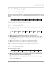
6.3.4.9 Drive/Head Register (1F6h)
This register contains the drive and head numbers. When executing an Initialize Drive Parameters command,
the content of this register defines the number of heads minus 1.
7 6 5 4 3 2 1 0
1 LBA 1 DEV HS3 HS2 HS1 HS0
• DRV is the binary encoded drive select number. When DEV=0, Device 0 is selected. When DEV=1,
Device 1 is selected.
• HS3 through HS0 contain the binary coded address of the head to be selected in CHS mode (e.g., if
HS3 through HS0 are 0011b, respectively, then head 3 will be selected). HS3 is the most significant bit.
In LBA mode this register contains bits 24-27 of the LBA. At command completion, this register is
updated to reflect the currently selected disk address.
• LBA is the binary coded address mode select. When L=0, disk addressing is by CHS mode. When L=1,
disk addressing is by LBA mode. This bit was set to zero when the ATA drive didn’t support LBA mode