


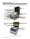
Unit 2: Technical Data
CT4i Series Operator Manual 2-7
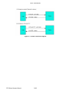
Note: When executing Windows hardware control, 3. and 4. above work as the connection.
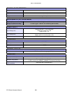
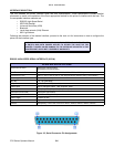
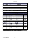
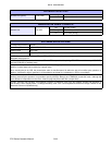
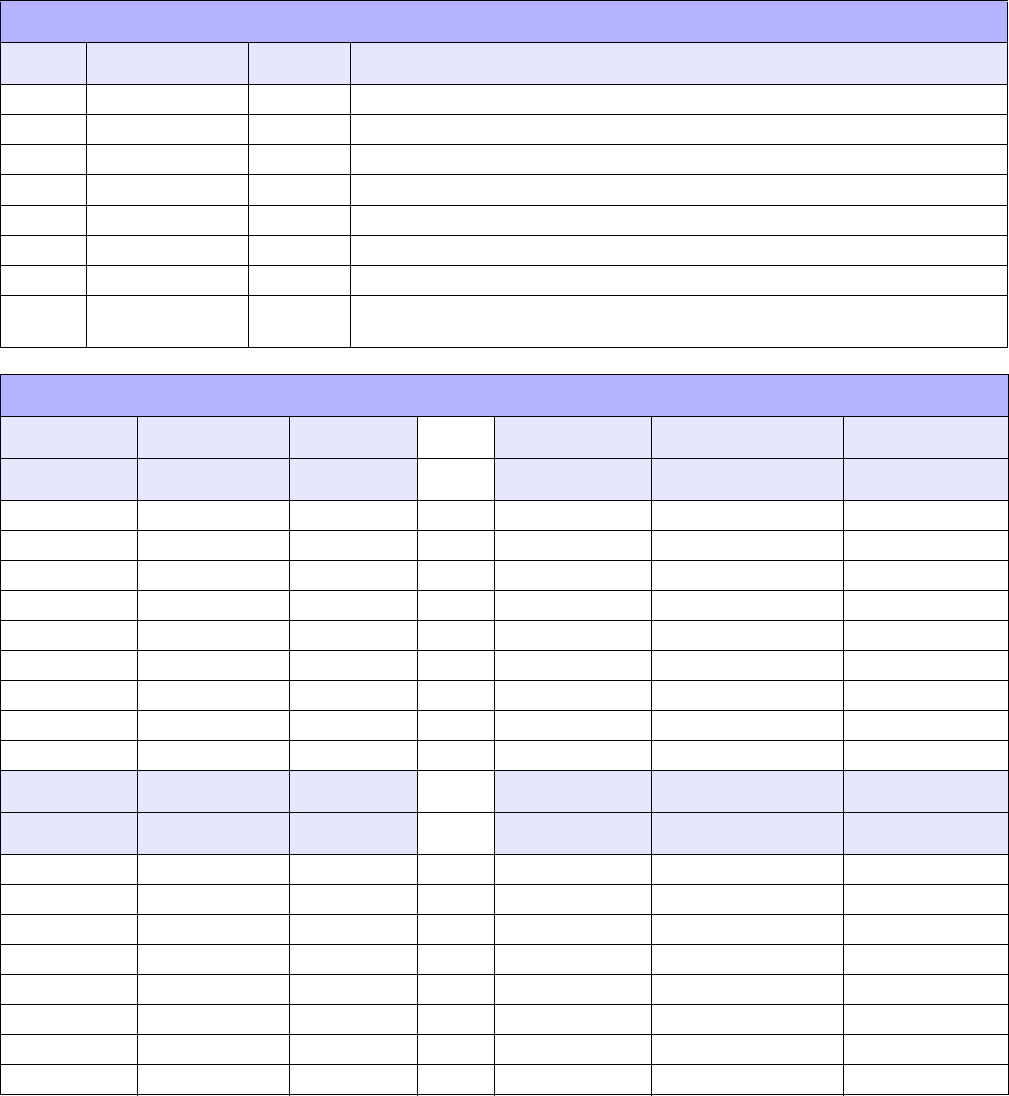
I/O SIGNALS
PIN# SIGNAL I/O DESCRIPTION
1 FG - Framework Ground
2 SD Output Data transferred from Printer to Host
3 RD Input Data transferred from Host to Printer
4 RS Output Goes to the Low state when an error occurs in the printer
5 CS Input Maintained at the High state
6 DR Input Maintained at the High state
7 SG - Signal Ground
20 ER Output Goes to the High state when printer is ready to receive data
Goes Low when printer is OFFLINE or errors have occurred in the printer
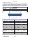
LINE CONNECTION
1. DB25P 2. DB9P
PRINTER HOST PRINTER HOST
FG 1 1 FG FG 1
SD 2 3 RD SD 2 2 RD
RD 3 2 SD RD 3 3 SD
RS 4 5 CS RS 4 8 CS
CS 5 4 RS CS 5 7 RS
DR 6 20 ER DR 6 4 ER
SG 7 7 SG SG 7 5 SG
ER 20 6 DR ER 20 6 DR
3. DB25P 4. DB9P
PRINTER HOST PRINTER HOST
FG 1 1 FG FG 1
SD 2 3 RD SD 2 2 RD
RD 3 2 SD RD 3 3 SD
RS 5 20 ER RS 4 6 DR
CS 4 6 DR CS 5 4 ER
DR 6 4 RS DR 6 7 RS
SG 7 7 SG SG 7 5 SG
ER 20 5 CS ER 20 8 CS