


Installing the Bridge Hardware
10
2.1 Overview: Hardware Installation
Here is an overview of the tasks for installing the bridge hardware. The references
are to the sections in this chapter that contain the detailed installation steps.
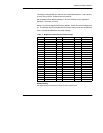
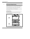
Setting the Modbus Plus Node Address (Section 2.2)
Before installing the bridge, set its Modbus Plus node address in switches on the
internal Modbus Plus card. The card is accessible by removing the bridge’s cover.
Note that every Modbus Plus node must have a unique address on the network.
The bridge is shipped with the node address set to the default of 1.
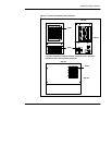
Setting the Ethernet Connector Jumper (Section 2.3)
Before installing the bridge, set its internal Ethernet Connector jumper to define
the type of physical cable connection you will be making to the Ethernet. The
bridge has these Ethernet connectors:
H IEEE 802.3 10Base--T unshielded twisted pair cable (UTP RJ--45)
H IEEE 802.3 10Base--5 thick cable (AUI DB--15S)
H IEEE 802.3 10Base--2 thin cable (BNC).
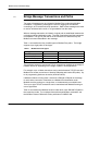
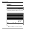
The Ethernet Connector jumper has two positions:
H Position 1: RJ--45/BNC connection
H Position 2: AUI connection.
The bridge is shipped with the jumper set to the default RJ--45/BNC position.
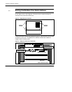
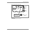
Mounting the Bridge Hardware (Section 2.4)
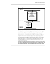
The bridge can be physically installed on a vertical wall panel or horizontal shelf
using mounting brackets supplied with the bridge. Be sure to provide clearance
for ventilation and access to the bridge’s rear panel connectors and indicators.
Connecting the Network and Power Cables (Section 2.5)
Connect the Ethernet and Modbus Plus cables to the bridge’s rear panel. Connect
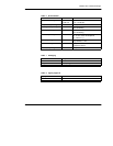
the power cable and apply power. The bridge has these connectors:
H Ethernet: RJ--45, AUI or BNC (according to your Connector Jumper setting).
H Modbus Plus: Two DB--9S for dual Modbus Plus drop cables.
H Power: Three--prong 110/220 V ac connector.