


Configuring the Bridge
28
3.2 Overview: Software Configuration
Here is an overview of the tasks for configuring the bridge. The references are to
the sections of this guidebook that show the detailed installation steps.
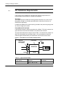
3.2.1 Setting the Ethernet Configuration
Configure the bridge’s IP address and other Ethernet parameters to allow your
host application to recognize the bridge.
Configuration With a BOOTP Server (Section 3.3)
If a BOOTP server exists, configure the server to recognize the bridge. When the
bridge is initially powered up, it will attempt for 30 seconds to connect to a BOOTP
server. If the server is found, the bridge will automatically configure for the
Ethernet connection. Note that you will still have to set up the mappings between
Ethernet and Modbus Plus devices, or you can create a host file for centralized
mapping which you can download.
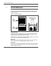
Configuration With the CFGUTIL Utility (Section 3.4)
If a BOOTP server is not available, you can use the internal CFGUTIL program to
configure the bridge. Connect a keyboard and VGA monitor to the bridge, start the
utility, and use it to setup the bridge’s IP and gateway addresses, and subnetwork
mask.
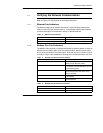
3.2.2 Setting the Modbus Plus and TCP/IP Address Mapping
Setup your bridge’s mapping tables to control the flow of traffic through the bridge.
Your mappings define the routing destinations for messages received by the
bridge on one network and passed through it to destinations on the other network.
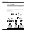
Setting the Mapping: TCP/IP to Modbus Plus (Sections 3.5 and 3.6)
Messages received by the bridge over TCP/IP contain a Destination Index
address byte in the range 1 ... 249 decimal. This byte corresponds to the
dest_idx field in Modbus Application Protocol commands issued in Modicon
panel software such as Concept and Modsoft. The bridge maps this byte to one of
249 possible Modbus Plus node destinations. You define the Modbus Plus node
address to be associated with each Destination Index byte value.
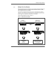
Setting the Mapping: Modbus Plus to TCP/IP (Sections 3.7 and 3.8)
Messages received by the bridge over Modbus Plus contain a routing byte in the
range 1 ... 255 decimal (the dest_idx field). The bridge maps this byte to one of
255 IP destinations. You define the IP address to be associated with each
Modbus Plus routing byte value.