


Configuring the Bridge
32
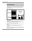
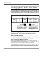
3.5 How Mapping Works: TCP/IP to Modbus Plus
Each Modbus Plus message destination is defined by a five--byte Modbus Plus
routing path. The use of the path is specific to each type of Modbus Plus device.
Refer to the guidebooks supplied with your Modbus Plus devices for details, or
refer to the Modbus Plus Network Planning and Installation Guide, part number
890 USE 100 00, for a general description of Modbus Plus routing paths.
Messages received by the bridge from Ethernet host nodes contain an embedded
Destination Index byte in the range 1 ... 255 decimal. This byte corresponds to the
dest_idx field in messages constructed by Modicon panel software such as
Modsoft and Concept.
The bridge uses the Destination Index byte to determine the type of routing to be
made.
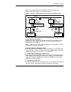
3.5.1 Destination Indexes 1 ... 249: Mapped Routing
The bridge uses Destination Indexes 1 ... 249 to map messages from a TCP/IP
node to a Modbus Plus destination node.
The bridge maps Destination Indexes in this range to one of 249 possible Modbus
Plus routing paths. Each Destination Index value maps to a location in a Modbus
Plus mapping table, which contains a five--byte Modbus Plus routing path to the
destination node.
Your configuration of the bridge must include entries into the bridge’s mapping
table to correlate the Destination Indexes to your routing paths for Modbus Plus
nodes in your application.
Section 3.6 describes how to set up the TCP/IP to Modbus Plus mapping table.