


Installing the Bridge Hardware
18
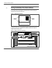
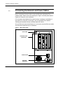
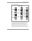
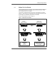
2.5 Connecting the Network and Power Cables
Before connecting the power cable, connect the Ethernet and Modbus Plus
network cables. Refer to the rear panel layout in Figure 7 and the panel detail in
Figure 8 for locations of the connectors.
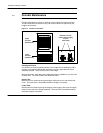
For information about Modbus Plus network design, including the availability of
drop cables for connection to the bridge, refer to the Modbus Plus Network
Planning and Installation Guide, publication 890 USE 100 00.
See your Ethernet network administrator for information about the Ethernet cables
and connectors applicable to your installation.
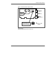
Figure 7 Rear Panel Layout
Power LED
Connector Panel
(see detail)
Power Switch
AC Power
Connector