


Installing the Bridge Hardware
19
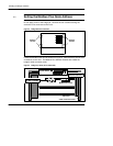
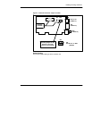
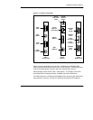
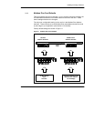
Figure 8 Connector Panel Detail
VGA
Video
PS/2
Mouse
Serial
Port
Modbus
Plus
Port B
Modbus
Plus
Port A
MB Plus
Active
Error
Channel B
Error
Channel A
RJ--45
Connection
Valid
TCP/IP
Network
Active
RJ--45
10Base--T
(UTP cable)
DB--15
10Base--5
BNC
10Base--2
Slot 1
Accessories
Slot 3
Modbus Plus
Slot 2
Ethernet
PS/2
Keyboard
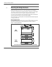
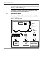
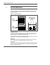
When you have completed the connection of the Ethernet and Modbus Plus
cables, set the bridge’s power switch to the 0 (OFF) position. Connect the power
cable to the bridge power connector and to the external power source.
Set the bridge’s power switch to the 1 (ON) position. The bridge’s Power LED
should illuminate, showing that power is applied and within specification.
The LED indicators for the Ethernet and Modbus Plus cards may also illuminate if
those networks are active. Section 2.7 describes the network LED indicators.