


Modbus Plus to Ethernet Bridge
2
1.1 Introducing the Ethernet to Modbus Plus Bridge
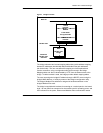
The Modicon Ethernet to Modbus Plus Bridge provides a transparent multipath
connection between Ethernet host applications and the Modbus Plus industrial
network. The bridge functions as an addressable node on each network,
managing the Ethernet and Modbus Plus protocols and translating messages
between the network applications in both directions.
Ethernet hosts can establish connections to the bridge and send messages
intended for Modbus Plus nodes. The bridge accepts the messages, creates
internal paths for the Modbus Plus transactions, waits for the Modbus Plus token
frame, and forwards the messages to the destination nodes. It receives the data
responses from the Modbus Plus nodes, returns them to the Ethernet hosts, and
closes the paths.
Messages sent to the bridge on either Ethernet or Modbus Plus contain an
embedded Modbus message, consisting of a function code and additional
information such as register addresses and data. The bridge uses the Modbus
function code to determine the type of internal path required for the transaction,
and opens a path if one is available. If a path is not available, a Modbus error
code (exception code) is returned by the bridge to the requesting node.
The bridge provides Modbus Data Master, Data Slave, Program Master, and
Program Slave paths as defined by the Modbus function codes in the messages.
It supports up to eight concurrent Data paths and eight concurrent Program paths.
The bridge supports full five--byte Modbus Plus routing, enabling transactions
through Modicon BP85 Modbus Plus bridges to Modbus Plus nodes on up to three
networks beyond the Ethernet bridge.
Note that Modbus Plus Global Data or Peer Cop messages are not supported
because those types of messages are passed as part of the Modbus Plus token
frame. The token frame is passed among nodes on the local Modbus Plus
network, but is not passed through any bridge devices to other networks.
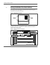
Figure 1 illustrates a typical bridge connection.