


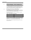
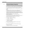


Configuring the Bridge
38
3.8 Setting the Mapping: Modbus Plus to TCP/IP
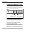
Each message from a Modbus Plus node contains a five--byte routing path field
(See Section 3.7). The bridge uses the third byte to index into its TCP Mapping
table, extracting an IP address from that entry.
You can edit the table to map the Modbus Plus routing path’s third byte to specific
IP addresses in your application.
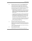
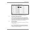
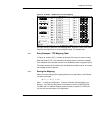
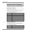
3.8.1 TCP Mapping Table Layout and Default Entries
The TCP Mapping table contains 255 fields, labeled TCP_1 through TCP_255.
These fields define IP addresses for messages (from Modbus Plus nodes) which
contain 1 through 255 decimal in byte 3 of the Modbus Plus message routing path.
By default the bridge automatically sets the first three bytes of each IP address to
match the first three bytes of the bridge’s IP address. (See Figure 14 and Section
3.4.3 for an example of configuring the bridge’s IP address.) The bridge sets the
fourth byte of the IP address mapping to the range 1 ... 255.
For example, if you configure the bridge’s IP address as:
205.167.7.65
the TCP Mapping table’s 255 locations will automatically default to:
TCP_1: 205.167.7.1
TCP_2: 205.167.7.2
. . . . . .
TCP_255: 205.167.7.255
Figure 18 shows an example of typical default TCP mapping, with one custom
routing entry made by the user.