


Configuring the Bridge
36
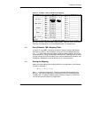
3.7 How Mapping Works: Modbus Plus to TCP/IP
The bridge contains an internal Modbus Plus to TCP mapping table with 255 entry
fields, each containing an IP address. Each message received by the bridge from
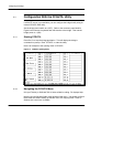
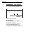
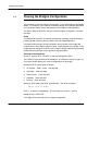
a Modbus Plus node contains a five--byte routing path field as shown in Figure 16.
Figure 16 Format of the Modbus Plus Routing Path Field
Bridge
Node
Address
1 ... 64
Bridge
Path
First IP
Routing
Byte
1 ... 255
MB+ Table
Routing
Byte
1 ... 249
Last
Routing
Byte
(Not Used)
Byte: 1 2 3 4 5
Defines index into this bridge’s
TCP Mapping table, and routes
message to the IP destination
stored in that table location.
If IP destination is another
TCP/IP--MB+ bridge, this byte
routes message to the MB+
node address in that bridge’s
MB+ Mapping table.
OPTIONALREQUIRED
1 ... 8
Bytes 1 and 2. Bridge Node Address and Path
The first byte in a message initiated from a Modbus Plus node to the bridge
addresses the bridge. The second byte opens a path within the bridge.
Byte 3. First Bridge’s IP Routing
The third byte corresponds to the dest_idx field in Modbus commands. This
byte indexes the bridge’s TCP Mapping table. The bridge extracts the IP address
at that table location and forwards the message to the IP destination.
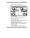
Byte 4. Second Bridge’s Modbus Plus Routing
Byte 4 allows the Ethernet network to operate as a link between two or more
bridges and their respective Modbus Plus networks. If the IP destination (from the
byte 3 table index) is not another bridge, the fourth byte is not used.
If the IP destination is another bridge, that bridge uses the fourth byte to index into
its MB+ Mapping table. It will extract a Modbus Plus routing path from the table
and forward the message to a destination node on its own Modbus Plus network.