


Installing the Bridge Hardware
12
2.2 Setting the Modbus Plus Node Address
Do not apply power to the bridge yet. Remove the four screws securing the
enclosure cover, and remove the cover.
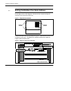
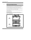
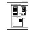
Figure 2 Bridge Enclosure Screws
Remove
Screws
Remove
Screws
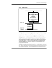
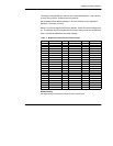
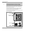
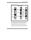
Locate the Modbus Plus card as outlined in Figure 3. Note that there are two sets
of switches on the card. The Modbus Plus address switches are toward the
bridge’s cable connector panel.
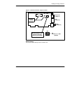
Figure 3 Bridge Top View (Cover Removed)
CPU Card
Ethernet Card
Modbus Plus Card
I/O Base Address
DO NOT CHANGE
Modbus Plus
Address Switches
Switch Detail
Cable Connector Panel