9·37
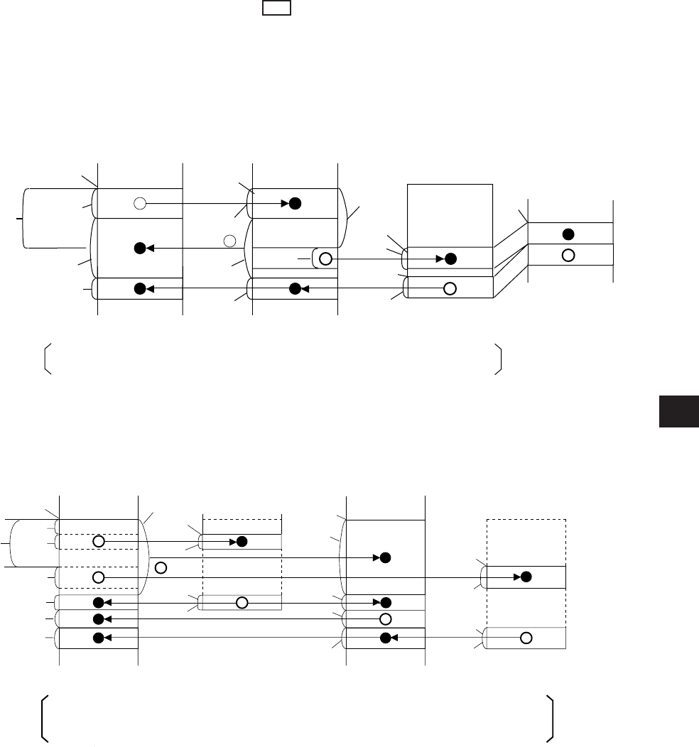
• An example of register link area map for the setting of the data link (the save memory function)
to slave station 01 and 03 and data link (the standard function) to slave station 02.
Total number of bytes of relay link area (
c
0 +
c
1 +
c
2) 256 bytes
c
2 +
h
2 64 bytes 0
a
2
c
0 +
c
1
Slave station 02
(8)
Data link
(the memory capacity save function)
(within JW-20CM)
Slave station 01
(8)
Data link
(the standard function)
Master station 00
(8)
(within
control module)
Total number of bytes of register link area (d
0
+ d
1
+ d
2
+ d
3
) 2048 bytes
0
b
1
d
0
+ d
2
+ d
3
0 b
3
d
0
+ d
1
+ d
2
i
1
+ d
1
512 i
3
+ d
3
512
Slave station 01
(8)
Data link
(the memory capacity save function)
(within JW-20CM)
Slave station 03
(8)
Data link
(the memory capacity save function)
(within JW-20CM)
Slave station 02
(8)
Data link
(the standard function)
Master station 00(8)
i
+
i
• Number of receiving bytes of slave station (h1 to hn, i1 to in)
Select self-setting or “same as number of sending bytes (c1 to cn, d1 to dn)” according to parameter
(007720 to 007723) of slave station.
• Number of offset bytes can be set exceeding the number of sending bytes of the master station.
a 1, a n c 0 and b 1, b n d 0
(3) When the master station and slave stations are all JW-20CM and both data link (the
standard function) and data link ( V5 memory capacity save function) are set among
slave stations.
Set signs below by the parameters of the master station (page 9·22, 33 and 34).
• An example of a relay link area map for the setting of the data link (standard function) for slave
station 01 and the data link (memory capacity save function) to slave station 02.


