


13·23
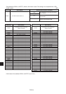
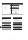
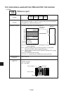
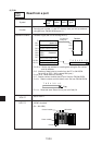
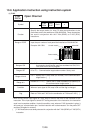
Setting range for "S"
· Rising edge of the input signal (OFF to ON) [ 3]
· S+3 to S+11 are transferred regardless of the input signal condition.
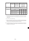
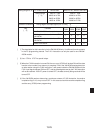
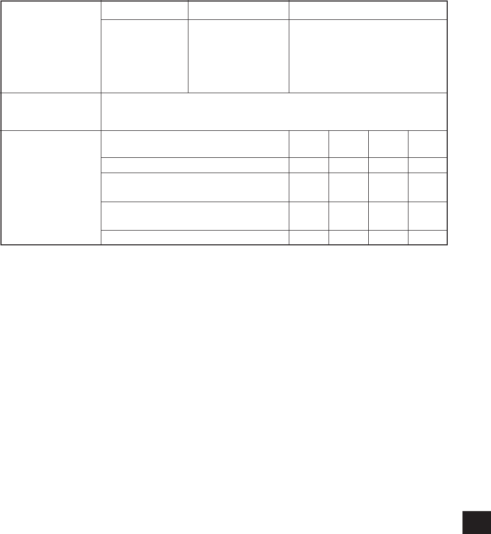
Operation conditions
Flag
PC model name W701H/100H JW50/70/100, JW50H/70H/100H
Setting range
[ 2]
0000 to 1566
b0000 to b1766
09000 to 09766
19000 to 19766
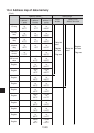
0000 to 1566
b0000 to b1766
09000 to 09766
99000 to 99766
E0000 to E1766
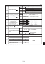
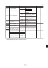
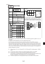
Contents
No ZW/JW-20CM on the option board
Waiting for a data transfer to a ZW/
JW-20CM on the option board
Completed a data transfer to a ZW/
JW-20CM on the option board
None of the above.
Non-carry
07354
0
1
0
0
Error
07355
1
0
0
0
Carry
07356
0
0
1
0
Zero
07357
0
0
0
0
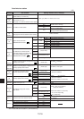
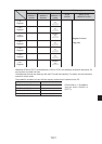
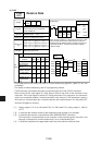
[ 1] The description for this instruction is for the ZW/JW-20CM only. It is different from the contents
in the PC programming manual. The F-200 instruction can only be used for one ZW/JW-
20CM module.
[ 2] Use 0730 to 0737 for special relays.
[ 3] When the F-200 instruction is turned ON, the non carry (07354) will be kept ON until the data
transfer to the number 2 port memory is complete. If the F-200 instruction is turned ON while
the non carry is ON, the data following this instruction will be invalid.
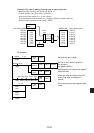
Note: The F-200 instruction will not receive a response from the opposite station. Use the data link
information for the response. Or, create a system for the data receive station to respond to
the reception of the F-200 instruction.