


4-1
CHAPTER 4
INTERFACE
This chapter describes information that is required when using the printer connected to a host, such
as the serial and parallel interface specifications.
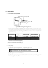
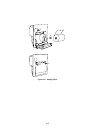
4.1 CONNECTOR TERMINAL LAYOUT
1. Interface and power connector terminal layout
Connector (plug) : XG4A-4032(Omron)
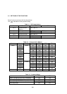
Connector signal layout
(!signal name indicates Active Low.)
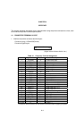
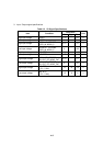
Table 4-1 Connector Terminal Assignment
No. Signal name Direction Description
1 !STROBE In Parallel data input
2 to 9 DATA0 to 7 In High:1, Low:0
10 !ACK Out Acknowledge
11 BUSY Out Busy to read
12 PE Out Paper empty
13 SEL OUT Out Online High
14 !ERROR Out Error
15 !RESET In Reset (Valid in Low 20ms)
16 TxD Out Serial data ouput
17 RxD In Serial data input
18 RTS Out RS-232C Request to send
19 CTS In RS-232C Clear to send
20 NEAR_A Out Paper near end ⋅ A (+)
21 NEAR_C In Paper near end ⋅ C (+)
22 NEAR_K − Paper near end ⋅ K (−)
23 NEAR_E − Paper near end ⋅ E (−)
24 NEAR_OUT Out Paper near end signal
25 !FEED_IN In Feed signal
26 GND − Ground
27 SEL_LED+ Out SEL LED on (+)
28 SEL_LED- Out SEL LED on (−)
29 to 34 V+ − Power (+)
35 to 40 V− − Power (−)
∗ Connect to all the No.29 to 34 and No.35 to 40 terminal when supplying the power