4-3
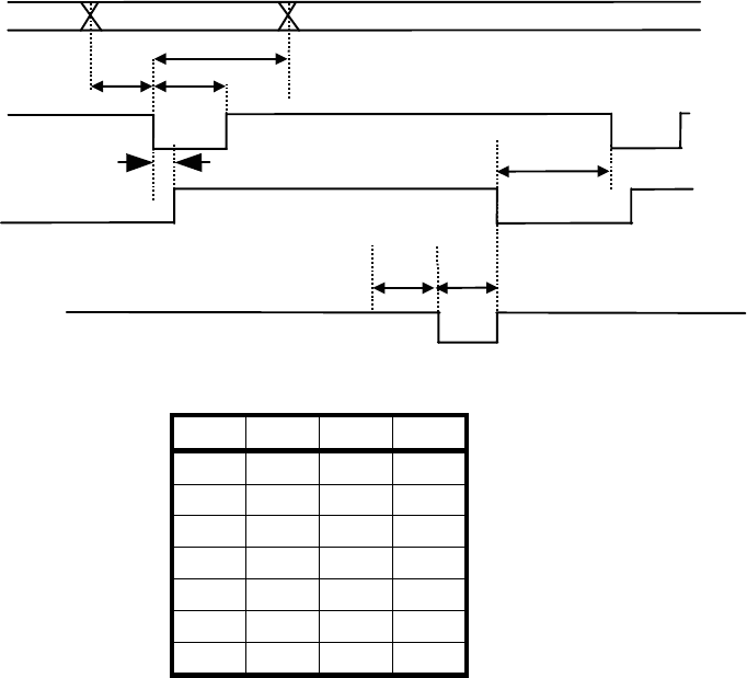
4.2 PARALLEL INTERFACE
1. Data input timing
T5
T4
T3
T2T1
DATA0 to 7
BUSY
T6
T7
STROBE
A
CK
Min. Max. Unit
T1 0.1 − µs
T2 0.5 − µs
T3 0.5 − µs
T4 − 0.5 µs
T5 0 − µs
T6 0.5 − µs
T7 − 1.0 µs
4.3 SERIAL INTERFACE
1. Hardware control
The RTS signal (Low or High) controls the transmission of the data from a host computer.
When the data stored in the input buffer of the printer exceeds 4,046 bytes, the RTS signal turns
Low.
Once the RTS signal turns Low, the host computer stops to transmit the data.
If the data stored in the input buffer of the printer falls below 3,995 bytes, the RTS signal turns
High.
Once the RTS signal turns High, the host computer resumes transmitting the rest of the data.
∗ When the printer fails (for example, paper-out), the RTS signal also turns Low.
And then, after the printer gets back to normal, the RTS signal turns High.


