


Ethernet-DK
Rev. 0.6 25
6.3. Stage 3—Configuring MAC and IP Addresses over the Serial Port
In the first two stages of the demo, we learned how to generate firmware for an embedded web server using the
TCP/IP Configuration Wizard and access the embedded server from a web browser. In this stage, we will learn
how to dynamically configure the IP address over the serial port.
6.3.1. Configuring the Target Board Jumpers for UART communication.
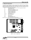
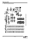
To enable UART communication on the C8051F120 Target Board, jumpers J6 and J9 must be shorted. See
Figure 27 for the location of J6 and J9.
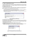
6.3.2. Modifying the Firmware to Enable the Serial Port
The simple web server firmware generated by the TCP/IP Configuration Wizard does not support configuring the IP
address over the serial port. In order to configure the MCU using the serial port, the firmware must be modified.
The web-server-3 project in the examples folder has been created to demonstrate an example of configuration
using the serial port. The following list outlines the functionality that has been added to web-server-3:
VDD Monitor is enabled as a reset source because firmware needs to write/erase Flash memory.
UART1 Initialization routine uses Timer 1 for baud rate generation.
UART1 is assigned to P0.0 and P0.1 in the Crossbar.
The stdio.h header file is included to allow use of string formatting functions such as printf().
The ipconfig() routine is used to configure the MAC address.
The global ip_address[4] variables is added in the Scratchpad area of Flash to store the programmed MAC
Address. The Scratchpad area is used to store the variable because it can be erased and re-written without
interfering with program code.
The global first_time variable is stored in Flash to keep track of whether the IP address has been programmed.
The following instructions show how to load the web-server-3 project:
1. Halt the MCU by clicking the Stop button in the toolbar
, selecting
Debug
Stop
from the menu, or pressing the
shortcut key
F4
.
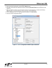
2. Close the current open project using the ProjectClose Project menu command.
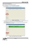
3. Open the web-server-3 project using the ProjectOpen Project menu command. The web-server-3 project
workspace is located by default in C:\SiLabs\MCU\Examples\C8051F12x_13x\Ethernet\HTTP\web-server-3
directory.
4. Build the project. This can be done by clicking on the Build/Make Project button in the toolbar, selecting
ProjectBuild/Make Project from the menu, or pressing the F7 shortcut key.
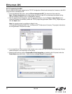
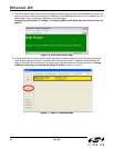
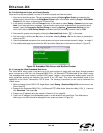
5. If not already connected, click the Connect button in the toolbar or select DebugConnect from the menu.
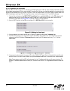
Note: If you receive the error message “Communication could not be established with the specified serial
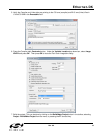
adapter”, open the Connection Options Dialog by selecting OptionsConnection Options from the
menu. Verify that the USB Debug Adapter is selected and that the debug interface is set to JTAG.
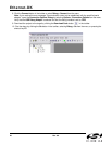
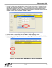
6. Download the project to the target by clicking the Download Code button in the toolbar.
7. Run the demo by clicking the Go button in the toolbar
, selecting
Debug
Go
from the menu, or pressing the
shortcut key
F5
.