


Ethernet-DK
Rev. 0.6 3
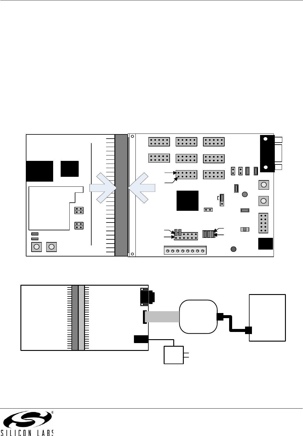
3. Hardware Setup
The following instructions illustrate how to setup the hardware included with the kit.
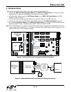
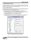
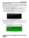
1. Connect the AB4 Ethernet Development Board to the C8051F120 Target Board at J24 (Figure 2). Apply
slight pressure to ensure the mating 96-pin connectors are firmly connected.
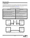
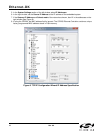
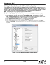
2. Using the ribbon cable, connect the USB Debug Adapter to the C8051F120 Target Board at the JTAG
header as shown in Figure 3.
3. Connect one end of the provided USB cable to any available USB port on the PC (Figure 3).
4. Connect the other end of the USB cable into the USB connector on the USB Debug Adapter (Figure 3).
5. Connect the ac/dc Power Adapter to the C8051F120 Target Board at P1 (Figure 3). This connection should
power both boards. Power is indicated by the "PWR" LED on the C8051F120 TB.
Note: The 'F120TB places a 2 resistor in series with the power supply net powering the AB4 Board. We recom-
mend replacing this resistor with a 0 resistor to prevent large voltage drops, possibly triggering a V
DD
Monitor reset, when current demand increases.
Figure 2. Embedded Ethernet Development Board Attachment
Figure 3. Embedded Ethernet Development Kit Debug Connections
J1
JTAG
P1
J24
J11
J3
J23
PWR
P1.6
J5
J9
J20
Pin 1
Pin 2
J22
Pin 1
Pin 2
J4
P3.7
RESET
J8J10 J6
Pin 1
Pin 2
Port 0 Port 2
Port 4
Port 7
Port 1
Port 3Port 6Port 5
J21
MONEN
C8051F12x
C8051F120
Target Board
RJ45
CP2200
AB4 Ethernet
Development
Board
LED1
LED2
SW2 SW1
J6
J5
J3
J4
Prototyping
Area
R1
USB Port
USB
Debug
Adapter
Ribbon
Cable
USB
Cable
PC
AC / DC
Adapter
C8051F120
Target Board
JTAG
AB4 Ethernet
Development
Board