


Ethernet-DK
26 Rev. 0.6
6.3.3. Programming the IP Address
Now the MCU will be running the new firmware and blinking the green LED (P1.6) to indicate that the IP address
has not been programmed. In this mode, the MCU is waiting for the user to initiate the update by connecting to the
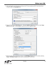
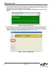
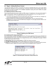
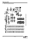
serial port and pressing any key to start. Figure 21 shows the output seen on a UART terminal screen when the
MCU is waiting for user input. The following instructions show how to program the IP and MAC addresses.
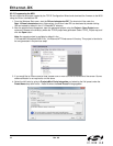
1. Connect the serial port on the C8051F120 Target Board to an available COM port on the PC using a serial
cable (included in kit). If the PC does not have a COM port, a USB-to-UART bridge such as the CP210x
Evaluation Kit available at www.silabs.com can be used as a virtual COM port.
2. Open a UART terminal on the PC and configure it for 9600 Baud 8-N-1 communication.
Figure 21. Waiting for User Input
3. Once connected, you should see the text in Figure 21 appear on the screen. Press any key.
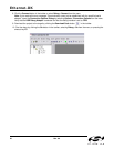
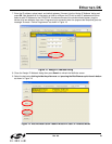
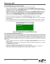
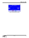
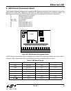
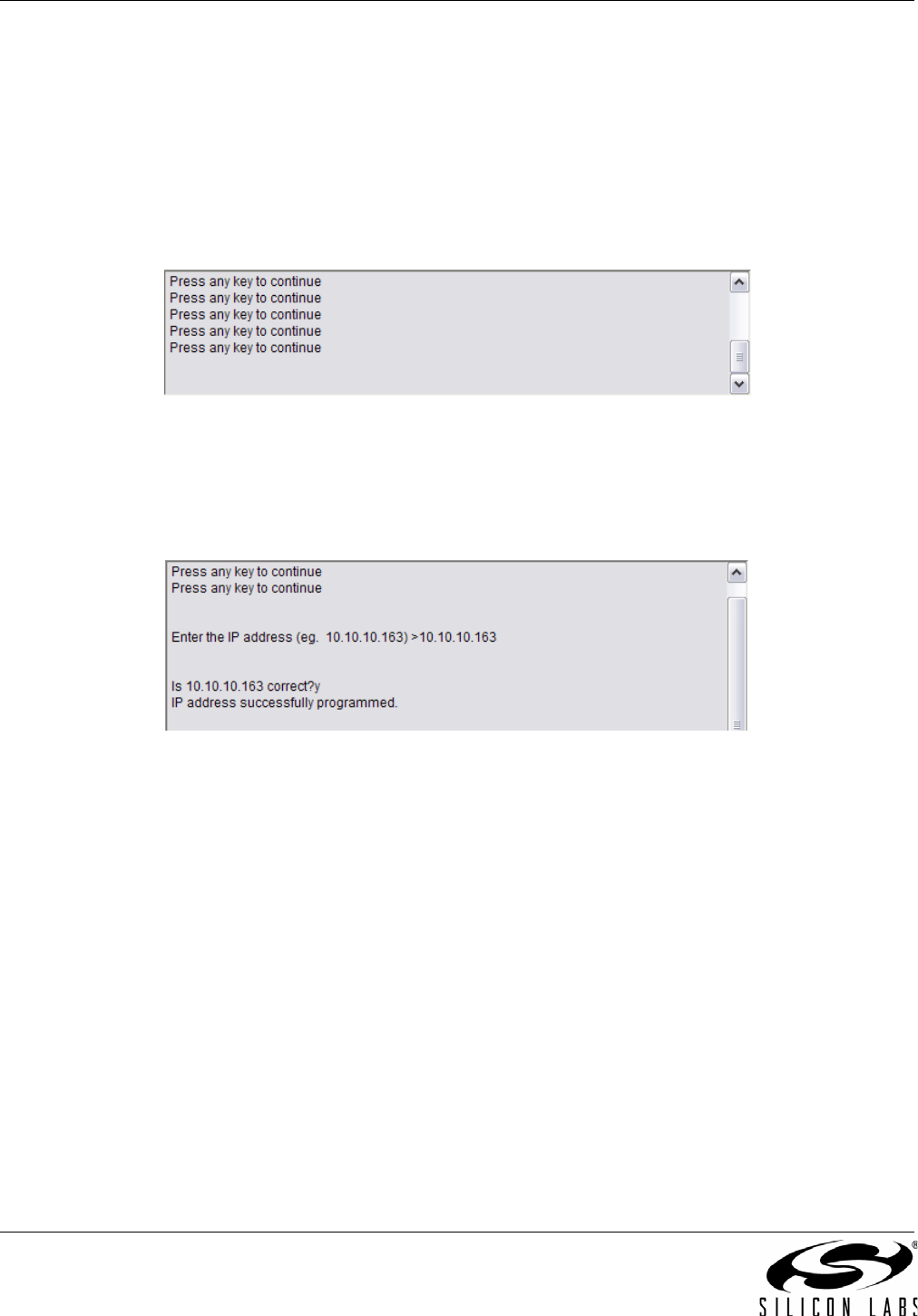
4. The MCU will prompt you to specify and verify an IP address. Figure 22 shows an example of successful
programming of the IP address. Press any key after entering the IP address and use “y” or “n” for the
confirmation.
Figure 22. Successful Programming of IP Address
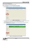
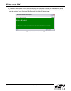
5. If programming is successful, the green LED on the C8051F120 Target Board will stop blinking and the web
server will start. You should now be able to ping the embedded web server or access it from a web browser.
Note: Once programmed, the MCU will not prompt for the IP address until the next firmware download. To
force an IP address update hold the SW2 (P3.7) switch on the C8051F120 Target Board down and reset the
MCU.