


99-00360-02 REV A0 Room Control Module Installation Guide for the 3000i 9
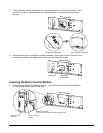
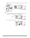
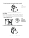
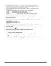
6 Reach inside the cabinet and attach the serial controller metal housing to the inside of the
front panel. To do this, fit the two partially inserted screws on the metal housing into the
keyholes on the front panel.
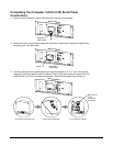
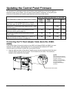
Connecting the I
2
C Control Panel Flash Cable (Serial No.
07000-07999)
If the last four digits of the serial number on your 3000i are between 07000 and 07999, you must
connect the I
2
C control panel flash cable to the SC7 serial controller before you can update the
control panel firmware.
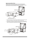
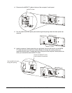
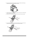
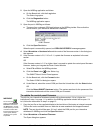
1 Open the right-hand door of the cabinet. Partially loosen the two screws that attach the serial
controller metal housing to the front panel. Two or three turns will suffice. The screws are
located on the outside of the front panel.
Partially loosen both screws
2 Reach inside the cabinet, behind the front panel. Lift the serial-controller metal housing up
and then back to release it from the keyholes on the panel.
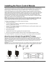
NOTE:
Several figures show the
top half of the cabinet
removed for illustration
p
urposes. However, yo
u
should leave the screen
and the top half of the
cabinet attached throughout
the installation procedure.
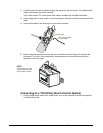
NOTE:
A
void pinching any of the
cables between the metal
housing and the cabinet.