


10 Room Control Module Installation Guide for the 3000i 99-00360-02 REV A0
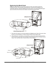
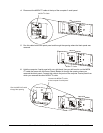
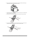
3 Carefully lower the serial controller through the opening in the front panel. The cables should
remain connected to the serial controller.
You’ll notice that the I
2
C control panel flash cable is bundled with the DB9 serial cable.
4 Using cutting pliers or wire cutters, cut the tie wraps as required to free the control panel flash
cable.
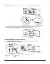
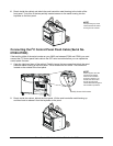
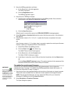
5 Connect this cable to the vertical jack on the serial controller.
I C Control Panel
Flash Cable
Vertical Jack
2
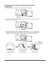
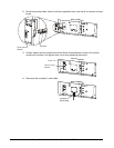
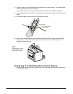
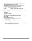
6 Reach inside the cabinet and attach the serial controller metal housing to the inside of the
front panel. To do this, fit the two partially inserted screws on the metal housing into the
keyholes on the front panel.
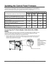
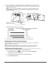
Connecting to a Third-Party Room-Control System
1 Plug the 3000i power cable into a power outlet, turn on the computer, and take the projector
out of Standby mode.
NOTE:
A
void pinching any of the
cables between the metal
housing and the cabinet.