


99-00360-02 REV A0 Room Control Module Installation Guide for the 3000i 1
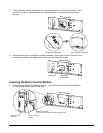
Installing the Room Control Module
These instructions explain how to install the SMART Room Control Module (part No. 3000i-RCM). For
information about programming the module to work with a third-party system, refer to the Room Control
Module Integration Guide for the Rear Projection SMART Board™ 3000i Interactive Whiteboard.
You can use a third-party room-control system to change the projector settings for a Rear Projection
SMART Board 3000i interactive whiteboard. However, when used on its own, a third-party room-control
system doesn’t provide access to the many features available from the control panel on the 3000i. To
provide an interface between the room control system and the 3000i, you need the SMART Room
Control Module. You can then use the control panel or the room control system to change the standby
state, source, display and volume settings for the 3000i.
NOTE: Check that the last four digits of the serial number for your 3000i are greater than 05000. The
Room Control Module only works with SMART Board 3000i interactive whiteboards that have a serial
number greater than 05000, because these units contain the SMART X-Port™ 20 switch.
The Room Control Module kit for the 3000i contains the following:
• the Room Control Module
• a custom straight-through MOD4 I
2
C cable with RJ11-6 (RJ12) connectors at both ends
(part No. 93-199-00) and a tie wrap
• a custom I
2
C flash adapter cable (part No. 93-00350-00) only for use if the serial number on your
3000i is between 05000 and 05999
• an anti-static wrist strap
• the warranty document
• a diskette with the hex file for upgrading the control panel firmware
• the Room Control Module Installation Guide and Room Control Module Integrator’s Guide
You’ll need a Phillips® No. 2 screwdriver and cutting pliers or wire cutters to perform the installation.
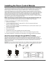
About the Custom Straight-Through MOD4 I
2
C Cables
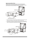
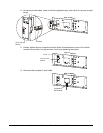
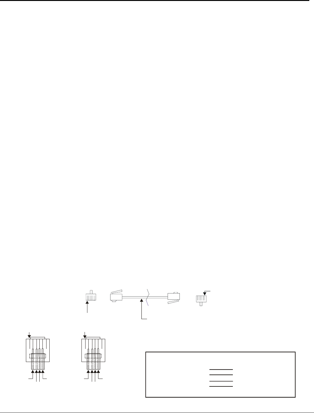
Before you install the Room Control Module in the patch panel, you need to connect two cables. We
supply one of the cables and you must reroute the other from inside the cabinet. Both are custom
MOD4 I
2
C cables that use RJ11-6 (RJ12) connectors with four colored wires attached and identical pin
assignments at both ends. The pin assignments for the connectors, shown below, are vital for the
cables to work correctly.
WARNING: This is a custom straight-through cable, not a standard crossover telephone cable. Using a
telephone cable instead of this custom cable could damage the Room Control Module and the 3000i.
Connector 1
Pin 1
Connector 2
Pin 1
MOD4 I C Cable
2
Pin 1
Black
Red
Yellow
Green
Pin 1
Black
Red
Yellow
Green
Connector 1
Connector 2
Pin 1
Pin 2
Pin 3
Pin 4
Pin 5
Pin 6
Pin 1
Pin 2
Pin 3
Pin 4
Pin 5
Pin 6
Black
Red
Yellow
Green
Connector 1 Connector 2
Black
Red
Yellow
Green
(Blue, not used)
(White, not used)
(Blue, not used)
(White, not used)