


99-00360-02 REV A0 Room Control Module Installation Guide for the 3000i 5
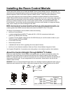
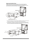
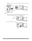
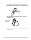
7 Tilt the computer 2 serial panel and pull it outside the cabinet. As you pull the panel out, flip it
so the RJ11-6 (RJ12) connectors remain inside the cabinet. The front of the panel should
face you.
Pull it outside the cabinet
Tilt the panel diagonally
R
e
a
r
o
f
C
a
b
i
n
e
t
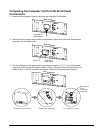
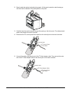
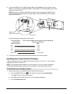
8 Partially tighten the four screws that hold the computer 2 serial panel in place. Once all of the
screws are in position, fully tighten them. Avoid over-tightening the screws.
Computer 2
Serial Panel
Screw x 4
R
e
a
r
o
f
C
a
b
i
n
e
t
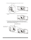
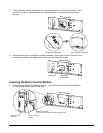
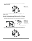
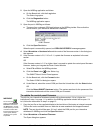
Inserting the Room Control Module
1 Connect the two MOD4 I
2
C cables to the RJ11-6 (RJ12) jacks on the Room Control Module.
You can connect either cable to either jack.
R
e
a
r
o
f
C
a
b
i
n
e
t
RJ11-6 (RJ12)
Jacks
Room Control
Module
T
h
i
s
d
e
v
i
c
e
c
o
m
p
l
i
e
s
w
i
t
h
p
a
r
t
1
5
o
f
t
h
e
F
C
C
r
u
l
e
s
.
O
p
e
r
a
t
i
o
n
i
s
s
u
b
j
e
c
t
t
o
t
h
e
C
a
u
s
e
h
a
r
m
f
u
l
i
n
t
e
r
f
e
r
e
n
c
e
,
a
n
d
(
2
)
T
h
i
s
d
e
v
i
c
e
m
u
s
t
a
c
c
e
p
t
a
n
y
i
n
t
e
r
f
e
r
e
n
c
e
r
e
c
e
i
v
e
d
,
i
n
c
l
u
d
i
n
g
i
n
t
e
r
f
e
r
e
n
c
e
t
h
a
t
m
a
y
c
a
u
s
e
u
n
d
e
s
i
r
e
d
o
p
e
r
a
t
i
o
n
.
T
h
is
d
e
v
i
c
e
c
o
m
p
l
ie
s
w
i
th
p
a
r
t
1
5
o
f
th
e
F
C
C
r
u
l
e
s
.
O
p
e
r
a
t
io
n
is
s
u
b
j
e
c
t
to
t
h
e
C
a
u
s
e
h
a
r
m
f
u
l
i
n
t
e
r
fe
r
e
n
c
e
,
a
n
d
(
2
)
T
h
is
d
e
v
i
c
e
m
u
s
t
a
c
c
e
p
t
a
n
y
i
n
t
e
rf
e
r
e
n
c
e
r
e
c
e
i
v
e
d
,
i
n
c
lu
d
in
g
i
n
te
r
f
e
r
e
n
c
e
t
h
a
t
m
a
y
c
a
u
s
e
u
n
d
e
s
i
re
d
o
p
e
r
a
t
io
n
.
MOD4 I C Cables
(You can connect either cable to either jack)
2