


Functional Overview
2-12 Copyright © 2006 ARM Limited. All rights reserved. ARM DDI 0389B
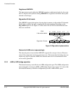
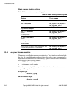
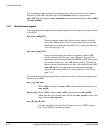
Static memory clocking options
Table 2-1 lists the static memory clocking options.
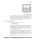
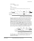
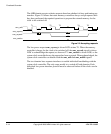
2.3.4 Low-power interface operation
The memory controller has two low-power interfaces. These interfaces indicate whether
the clock for a specific domain can be switched off to reduce power consumption. It is
expected that these interfaces are controlled by a system clock controller. One interface
controls each of the following domains:
• AHB clock domain
• static memory clock domain.
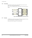
Each domain uses a simple three signal interface to indicate whether the clocks are
required. The signals consist of:
a request input
<domain>_csyreq
an acknowledge output
<domain>_csysack
Table 2-1 Static memory clocking options
Options Tie-off values
Fully synchronous
hclk = smc_mclk0 smc_async0 = smc_msync0 = 1
smc_a_gt_m0_sync = 0
Synchronous multiples
hclk = n x smc_mclk0
where:
n = integer value
smc_async0 = smc_msync0 = 1
smc_a_gt_m0_sync = 0
m x hclk = smc_mclk0
where:
m = integer value
smc_async0 = smc_msync0 = 1
smc_a_gt_m0_sync = 1
Asynchronous
Extra registers are used to avoid metastability when
crossing the asynchronous clock boundary.
smc_async0 = smc_msync0 = 0
smc_a_gt_m0_sync = 0