


AR-B1474 User¡¦s Guide
2-9
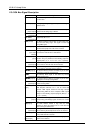
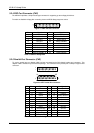
(8) MODEM Status Register (MSR)
Bit 0: Delta Clear to Send (DCTS)
Bit 1: Delta Data Set Ready (DDSR)
Bit 2: Training Edge Ring Indicator (TERI)
Bit 3: Delta Receive Line Signal Detect (DSLSD)
Bit 4: Clear to Send (CTS)
Bit 5: Data Set Ready (DSR)
Bit 6: Ring Indicator (RI)
Bit 7: Received Line Signal Detect (RSLD)
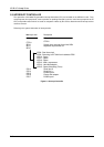
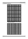
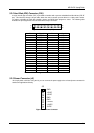
(9) Divisor Latch (LS, MS)
LS MS
Bit 0: Bit 0 Bit 8
Bit 1: Bit 1 Bit 9
Bit 2: Bit 2 Bit 10
Bit 3: Bit 3 Bit 11
Bit 4: Bit 4 Bit 12
Bit 5: Bit 5 Bit 13
Bit 6: Bit 6 Bit 14
Bit 7: Bit 7 Bit 15
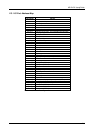
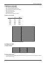
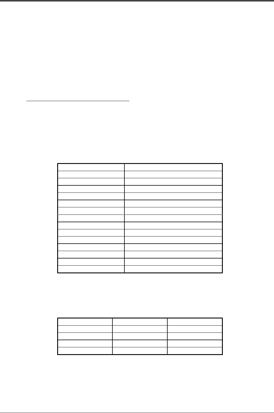
Desired Baud Rate Divisor Used to Generate 16x Clock
300 384
600 192
1200 96
1800 64
2400 48
3600 32
4800 24
9600 12
14400 8
19200 6
28800 4
38400 3
57600 2
115200 1
Table 2-8 Serial Port Divisor Latch
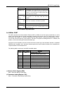
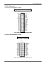
2.5 PARALLEL PORT
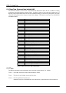
(1) Register Address
Port Address Read/Write Register
base + 0 Write Output data
base + 0 Read Input data
base + 1 Read Printer status buffer
base + 2 Write Printer control latch
Table 2-9 Registers’ Address
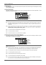
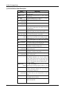
(2) Printer Interface Logic
The parallel portion of the SMC37C669 makes the attachment of various devices that accept eight bits of parallel
data at standard TTL level.