


AR-B1474 User¡¦s Guide
5-6
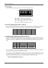
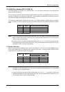
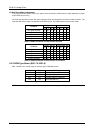
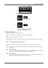
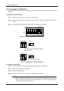
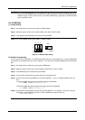
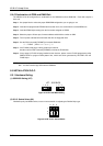
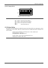
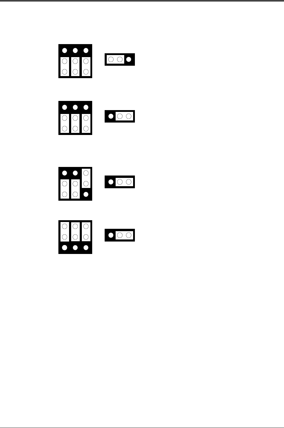
5.3.2 SSD Memory Type Setting (M1 ~ M3 & JP5)
M1, M2 & M3
EPROM (128KX8, 256KX8 and 512KX8)
5V FLASH (64KX8, 128KX8 and 256KX8)
(Factory Preset)
5V FLASH (512KX8 Only)
SRAM
M1, M2 & M3
M1, M2 & M3
1
2
3
A B C
1
2
3
A B C
1
2
3
A B C
M1, M2 & M3
1
2
3
A B C
1 2 3
JP5
1MX8 EPROM
(Only)
1 2 3
JP5
1 2 3
JP5
1 2 3
JP5
Figure 5-4 M1~M3 & JP5: Memory Type Setting
5.4 ROM DISK INSTALLATION
The section describes the various type SSDs’ installation steps as follows. The jumper and switch adjust as SSD’ s
different type to set.
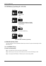
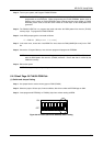
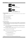
5.4.1 UV EPROM (27Cxxx)
(2) Switch and Jumper Setting
Step 1: Use jumper block to set the memory type as ROM (FLASH).
Step 2: Select the proper I/O base port, firmware address, disk drive number and EPROM type on SW1.
Step 3: Insert programmed EPROM(s) or FLASH(s) chips into sockets starting at MEM1.