


AR-B1474 User¡¦s Guide
2-10
(3) Data Swapper
The system microprocessor can read the contents of the printer’ s Data Latch through the Data Swapper by reading
the Data Swapper address.
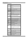
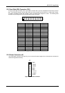
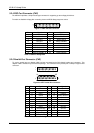
(4) Printer Status Buffer
The system microprocessor can read the printer status by reading the address of the Printer Status Buffer. The bit
definitions are described as follows:
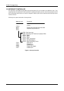
X X X
1234567 0
-ERROR
SLCT
PE
-ACK
-BUSY
Figure 2-2 Printer Status Buffer
NOTE: X presents not used.
Bit 7: This signal may become active during data entry, when the printer is off-line during printing, or when the
print head is changing position or in an error state. When Bit 7 is active, the printer is busy and can not
accept data.
Bit 6: This bit represents the current state of the printer’ s ACK signal. A 0 means the printer has received the
character and is ready to accept another. Normally, this signal will be active for approximately 5
microseconds before receiving a BUSY message stops.
Bit 5: A 1 means the printer has detected the end of the paper.
Bit 4: A 1 means the printer is selected.
Bit 3: A 0 means the printer has encountered an error condition.
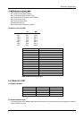
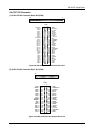
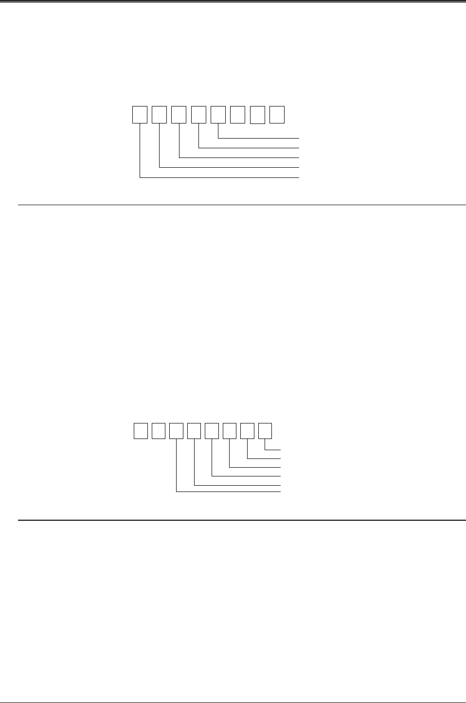
(5) Printer Control Latch & Printer Control Swapper
The system microprocessor can read the contents of the printer control latch by reading the address of printer
control swapper. Bit definitions are as follows:
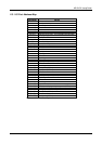
X X
1234567 0
STROBE
AUTO FD XT
INIT
SLDC IN
IRQ ENABLE
DIR(write only)
Figure 2-3 Bit’ s Definition
NOTE: X presents not used.
Bit 5: Direction control bit. When logic 1, the output buffers in the parallel port are disabled allowing data driven
from external sources to be read; when logic 0, they work as a printer port. This bit is write only.
Bit 4: A 1 in this position allows an interrupt to occur when ACK changes from low state to high state.
Bit 3: A 1 in this bit position selects the printer.
Bit 2: A 0 starts the printer (50 microseconds pulse, minimum).
Bit 1: A 1 causes the printer to line-feed after a line is printed.
Bit 0: A 0.5 microsecond minimum highly active pulse clocks data into the printer. Valid data must be present
for a minimum of 0.5 microseconds before and after the strobe pulse.