


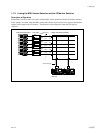

1-19 (E)
BKP-7933
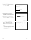
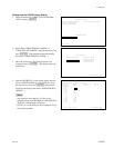
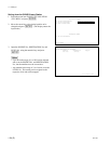
SONY ROUTING SYSTEM SETUP MENU BKP-7933 V1.00 STATION NUMBER 2
MODIFICATION COMMAND
A: SET UNIT LOCATION(CAM-CCU) B: SET UNIT LOCATION(CCU-RCP)
C: SET UNIT LOCATION(MSU)
K: RESET TO DEFAULT TABLE
MAINTENANCE COMMAND
Z: BKP-7933 CONFIGURATION
Ctrl-D RETURN
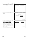
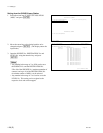
BKP-7933 CONFIGURATION BKP-7933 V1.00 STATION NUMBER 2
S-BUS CONFIGURATION
A: ROUTER PIX1 ASSIGN B: ROUTER WF1 ASSIGN
C: ROUTER PIX2 ASSIGN D: ROUTER WF2 ASSIGN
E: ROUTER PIX3 ASSIGN F: ROUTER WF3 ASSIGN
G: S-BUS TALLY H: BKP-7933 MODE
Ctrl-E RETURN TO MENU
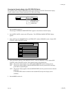
BKP-7933 CONFIGURATION BKP-7933 V1.00 STATION NUMBER 2
ROUTER PIX3 ASSIGN (FOR RCP Previw switch))
CNU GROUP No SOURCE No DESTINATION No LEVEL No
Master Source 0013 0015 1---
(Camera No.)
2 (13) 0000
2 (14) 0000
2 (15) 0000
2 (16) 0000
2 (17) 0000
2 (18) 0000
3 (19) 0000
3 (20) 0000
3 (21) 0000
3 (22) 0000
3 (23) 0000
3 (24) 0000
F1:F2: F3:PgUp F4:PgDn Ctrl-E RETURN TO MENU
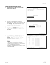
Setting from the S-BUS Primary Station
1. Select the menu item “Z:BKP-7933 CONFIGURA-
TION” and press [ENTER].
2. Select either “E:ROUTER PIX3 ASSIGN” or
“F:ROUTER WF3 ASSIGN” using the cursor key and
press [ENTER]. (The illustration shows the display
that selects “E:ROUTER PIX3 ASSIGN”. )
3. Move the cursor key to the desired position to be
changed and press [ENTER]. (The display enters the
input mode.)
4. Input the SOURCE No. of the master source and each
camera, DESTINATION No. and LEVEL No. using
the numeric keys and press [ENTER]. (The illustra-
tion shows the display that selects “E:ROUTER PIX3
ASSIGN”. )
m
. Any number in the range of 1 to 1024 can be
selected and set to the SOURCE No. and DESTINA-
TION No. without being consecutive.
. LEVEL No. can be freely set, but it cannot be set for
each camera number.
1-7. Setting Up