1-39 (E)
BKP-7933
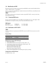
1-9. Modification of RCP
The video on the preview monitor can be selected by the PREVIEW switch of the RCP-700/701/720/721/
730/731. (Refer to section 1-7-4 for details.)
However, version check of the ROM that is installed in the board of the RCP side, and modification of the
board in the RCP are required.
n
If you want to switch the video on the preview monitor using the RCP-740/741, contact your local Sony
Sales Office/Service Center.
1-9-1. Checking ROM Version
Be sure to check that the ROM version for the MPU board of the RCP side is Ver. 2.00 or higher. When
the ROM needs to be replaced, contact your local Sony Sales Office/Service Center.
ROM Version
RCP-700/701 IC8/MPU-92: Ver. 2.00 or higher
RCP-720/721/730/731 IC10/MPU-79: Ver. 2.00 or higher
1-9-2. Modification of RCP-700/701
n
After this modification is implemented, the PREVIEW switch of the RCP-701 does not turn on even if it
is pressed.
Required Parts
Description Sony P/N Q'ty
Diode 1SS300-TE85L 8-719-024-81 1
Jumper wire __
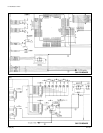
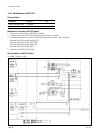
Modification Procedure (SW-752 Board)
1. Remove Q35 and Q36.
2. Cut the printed foil pattern between Q35 base and pin-18/IC4. (1)
3. Cut the printed foil pattern between Q35 emitter and Q34 emitter. (2)
4. Connect the three jumper wires by soldering.
Between pin-2/CN4 and pin-50/IC1 (3)
Between pin-5/CN5 and Q35 emitter (4)
Between Q35 collector and D1 anode (5)
5. Connect a diode 1SS300-TE85L to the soldering land of Q35 by soldering.
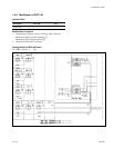
Setting Switch on MPU-92 Board
S4-2/MPU-92 board → ON
1-9. Modification of RCP


