1-42 (E)
BKP-7933
1-9-4. Modification of RCP-721
Required Parts
Description Sony P/N Q'ty
Resistor, Chip Metal 82 Z 1-216-625-11 1
Jumper wire __
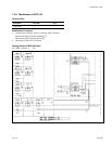
Modification Procedure (SW-752 Board)
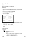
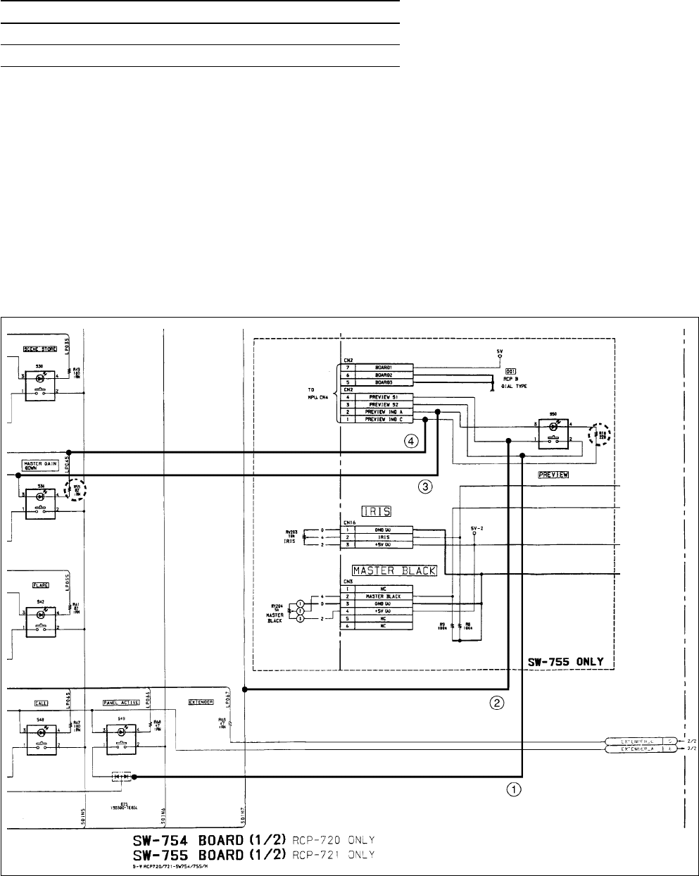
1. Remove the resistors R10 and R55/SW-755 board.
2. Connect a metal resistor 82 Z to the soldering land of R10, by soldering.
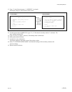
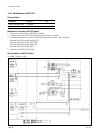
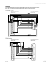
3. Connect the four jumper wires by soldering to the following locations. (SW-755 board)
Between pin-3/CN2 and D25 cathode (1)
Between pin-4/CN2 and pin-2/S24 (2)
Between pin-2/CN2 and pin-3/S36 (3)
Between pin-1/CN2 and R55 (4)
4. Disconnect CN101/CN-1187 board.
Setting Switch on MPU-92 Board
S4-7/MPU-79 board → ON
1-9. Modification of RCP


