


1-45 (E)
BKP-7933
Modification of AT-89 Board
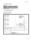
1. Connect a jumper wire between B7 pin/CN2 and B9 pin/CN2 of the AT-89 board of the CNU-700 by
soldering.
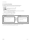
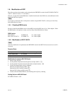
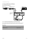
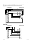
2. Remove the six screws and remove the rear panel. Remove the harness that is connected to the
connector CN12 on the MB-562 board and the connector CN15 on the CN-1001 board. Connect the
RS-422 harness that is supplied, instead of the removed harness.
n
Be careful that the either end of the RS-422 harness has the specified destination of connection.
The following labels are attached to the rear of the housing at both ends.
[15] → To CN-15/CN-1001 board
[12] → To CN-12/MB-562 board
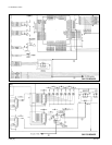
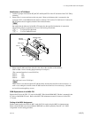
3. Remove the IF-480 board from of the first slot and set the switches as shown below.
S802 to S806: Insert a shorting plug between pin-2 and pin-3.
(The command interface is set to RS-422A.)
S901-4: ON
S901-5: OFF
S901-6: OFF
(The baud rate is set to 38.4 k bps.)
n
There can be a case that the optional IF-480 board has already been installed to the second slot. In
such a case, setting the switches on the IF-480 board in the second slot is not necessary. (Switches
are invalid even though they are set.)
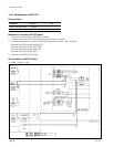
ROM Replacement of the MSU-700
Replace the IC10 on the CPU-171 board of the MSU-700 with the ROM MSU-700 that is mounted in the
IC socket of the ROM-25 board. Refer to the MSU-700 maintenance manual for removal of the CPU-
171 board.
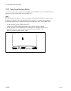
Setting of the MSU Assignment
Set the control mode to the LOCAL MSU mode (LOCAL mode) using the MSU assignment menu.
Refer to the BVP-900-series System Manual BKP-9901 (available separately) Section 3-4-3 “MSU
Assignment” for the setting procedure.
1-10. Using the BKP-7933 in the HD System
CN12
Rear panel
RS-422
Harness
MB-562 board
CN15
B3 x 5
B3 x 5
B3 x 5