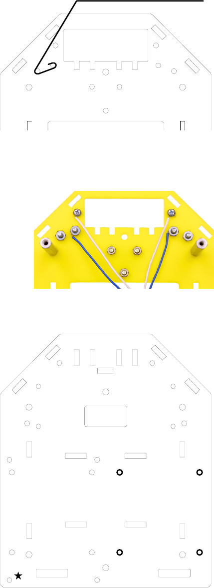
Chassis Assembly
Strip about 2” from one end of each 7” length of 18 AWG
insulated wire.
Hardware (for one side):
1 4-40 x 1/4” round standoff
1 4-40 x 1/4” screw
2 4-40 x 1/2” screws
2 4-40 washers
2 4-40 nuts
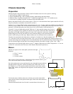
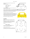
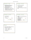
Mount the standoff in hole C, on the same side of the plate
as the caster, using the 1/4” screw.
A
B
C
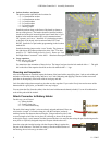
For holes A and B, put a washer on a 1/2” screw and put the screw through the plate from the side with the caster.
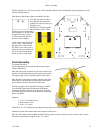
Attach a nut (on the side with the standoffs). Bend the stripped end of the wire around pins A and B as shown.
Fasten between the washer and the plate. Make sure that the section of the wire next to C is stripped. Place
additional bends in the wire to make an effective bump sensor.
Hold the plate so that the caster is on the bottom.
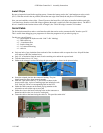
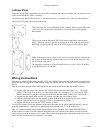
Connect one of the spare blue wires (from the light sensors) to A,
wrapping the 3/8” tinned end around the screw and fastening it under
the nut (on the opposite side of the chassis from the bumper wire).
Connect one of the spare white wires to C, fastening it under the
screw head (on the same side of the chassis as the blue wire).
Repeat the bumper installation on the other side.
Top Plate
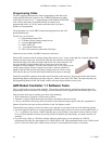
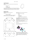
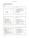
The picture at the right shows the top plate as seen from
above.
Note: this piece is not symmetric. Make sure that you are
holding the piece so that there’s a hole in the lower left
corner (marked by the star in the picture). If the hole is in
the lower right corner, flip the piece over.
Hardware:
4 4-40 x 1/2” standoffs
4 4-40 x 1/4” screws
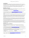
Insert the screws through the highlighted holes from
underneath, sticking up through the plate.
Attach the standoffs to the screws.
Double-check to make sure that with the standoffs sticking
up from the plate, you have a hole in the lower left corner.
16 11-3-2005


