AVR Robot Controller 1.1 Hardware Description
AVR Robot Controller 1.1 Hardware Description
The Level 1 Robot Kit ships with an ATmega16 microcontroller. The Atmel AVR microcontrollers are designed to
be pin- and code-compatible where possible. In this case, for example, you could substitute an ATmega8535 or
ATmega32. These chips will all function in the ARC board with minimal software changes (typically just a re-
compile), the primary difference being the amount of internal memory available. Please see Atmel’s site
(www.atmel.com) for a list and descriptions of available devices.
Power
Power can be any source from 6-24 volts DC. Pay attention to the polarity symbols near the power plug -- ground is
in the center, with +V applied at either end. The ARC board is protected against battery reversal with a diode. This
diode reduces the available power to the board and prevents destruction of the H-Bridge in case of accidental battery
reversal. If you want, you can use a polarized battery connector and solder it directly to the board and replace the
diode with a bare wire.
I/O Pins
The ATmega16 microcontroller has four 8-bit I/O ports and many peripheral functions that work through these I/O
pins. Port A also doubles as the analog input port. Port D doubles for many of the built in functions like serial I/O,
PWM and timers. Port B doubles as the programming interface.
The following table lists the I/O pins that are brought out to headers on the ARC board. (The expansion headers JP3
and JP10 are not included since they bring out all I/O port bits as well as power and ground.) Connection lists what
device or feature the robot communicates with. Physical Pin is the connection to the ATmega16. Functional Name
indicates how each connection is used in the programs. Input/Output describes the communication direction as
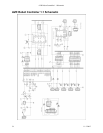
viewed from the ATmega16. Header is the text identifying that connection on the board. (See the schematic for pin
details.)
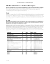
Connection
Physical
Pin
Functional
Name
Input/
Output
Header
Left bump sensor PA0 PA0 input LEFT (at front of board)
Right bump sensor PA7 PA7 input LEFT (at front of board)
Left distance sensor (Level 2) PA0 ADC0 input RIGHT (at front of board)
Right distance sensor (Level 2) PA7 ADC7 input RIGHT (at front of board)
Left light sensor PA1 ADC1 input LF (“left floor”)
Center light sensor (not included with kit) PA2 ADC2 input CF (“center floor”)
Right light sensor PA3 ADC3 input RF (“right floor”)
Left motor direction PC3 PC3 output LEFT (at back of board)
Left motor PWM PD4 OC1B output LEFT (at back of board)
Left motor channel A (encoder, Level 3) PD3 INT1 input LEFT (at back of board)
Left motor channel B (encoder, Level 3) PC2 PC2 input LEFT (at back of board)
Left servo (not included with kit) PC2 PC2 output LEFT (at back of board)
Right motor direction PC4 PC4 output RIGHT (at back of board)
Right motor PWM PD5 OC1A output RIGHT (at back of board)
Right motor channel A (encoder, Level 3) PD2 INT0 input RIGHT (at back of board)
Right motor channel B (encoder, Level 3) PC5 PC5 input RIGHT (at back of board)
Right servo (not included with kit) PC5 PC5 output RIGHT (at back of board)
Serial input PD0 RXD input JP5
Serial output PD1 TXD output JP5
Green “program” LED PB4 PB4 output PROG (green LED)
Option A PB6 PB6 ISP/JP9, A
Option B PB7 PB7 ISP/JP9, B
Option C PB4 PB4 ISP/JP9, C
11-3-2005 31


