


AVR Robot Controller 1.1 Assembly Instructions
Sockets, headers, and jumper
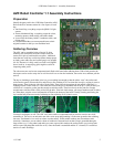
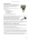
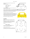
The picture on the right shows the locations for:
2 - 1x3 boardmount sockets
3 - 1x4 boardmount sockets
3 - 1x3 male headers
2 - 2x3 male headers
1 - 2x5 male header
1 - shorting jumper
Install the sockets along on the front of the board (as shown at
the top of the picture). The headers should be installed with the
shorter end of the pins inserted into the board. Install the 1x3 pin
headers in the locations marked JP5 (serial communications),
JP13 (power), and “servo.” Install the 2x3 pin headers (motors)
at the back of the board, in the locations marked LEFT and
RIGHT. Install the 2x5 pin header (programming) in the location
marked JP9.
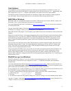
Install the shorting jumper on the “servo” header. The picture on
the right shows the jumper positioned to select “Bat.” The other
option is “5V.” Either setting is fine for Level 1. Please see “Left
and Right Motor Connectors” in the ARC 1.1 Hardware Description section for details.
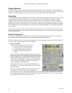
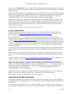
Large capacitors
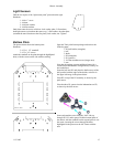
In this step you will install:
3 - 47uF capacitors
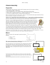
Pay attention to the orientation of these devices. The longer lead goes into the hole marked with a ‘+’. The gold
bar on the side of the capacitor should be on the side marked with a ‘-’ sign.
Cleaning and Inspection
After all components are installed, inspect the bottom of the board with a magnifying glass. Look at each solder pad
and make sure that the solder is shiny and has a “wet” look. Reheating and applying a touch of solder can rework
pads that are incompletely filled with solder or look gray and dull.
Look for solder bridges between pads or pins that are close together. If you used a fine tip iron and no more solder
than needed for a good joint, you shouldn’t have any bridges.
You can clean the flux (from the solder) from the board with denatured ethanol (alcohol). Use an old toothbrush to
scrub all the pads with the alcohol.
Attach Connector to Battery Holder
For this step, you will need:
1 - battery holder
2 - female crimp pins
1 - 1x3 connector housing
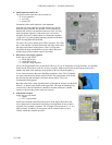
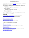
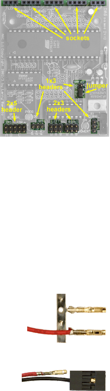
The ends of the battery holder’s wires are already stripped and tinned. Place one
wire into the “trough” of a female crimp pin, with the insulation just barely
reaching into the area between the two triangles. Using needle-nose pliers, fold
over one triangle to hold the wire in place for soldering (as shown in the picture
on the right). Apply a small amount of solder between the bare wire and pin, then crimp the pin closed using needle-
nose pliers or a specially-designed crimp tool. Repeat with the other wire.
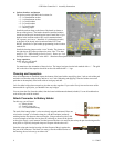
Insert the crimp pins into the housing with the flat part of the pin against the
flat part of the connector. The black wire must go into the middle location of
the housing; the red wire can go on either side.
8 11-3-2005