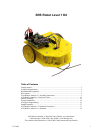
AVR Robot Controller 1.1 Assembly Instructions
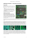
Small capacitors and LEDs
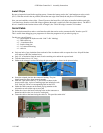
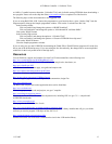
The picture on the right shows the locations for:
8 - 0.1uF capacitors
1 - red LED
1 - green LED
Orientation of the small capacitors is not important.
Note that one of the capacitors (second from the top) will be
under the microcontroller. Be sure that it sticks up no higher
than the DIP socket (to be installed in the next step). You may
need to bend the capacitor’s leads a bit to get it to sit close
enough to the board. Another option is to mount the capacitor
“lying down” by gently putting right angle bends into the leads
before inserting them into the board.
The red LED is power and the green LED is program. The LEDs
have a flat side that is oriented toward the near edge of the board
(the edge at the bottom of the picture). There is a long and a
short lead; the short lead should be near the edge of the board
and the longer lead toward the center of the board.
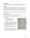
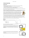
DIP sockets and voltage regulator
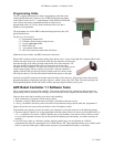
In this step you will install:
1 - 40-pin DIP socket
2 - 16-pin DIP sockets
1 - LM2940 voltage regulator
All ICs can be mounted directly on the board. However, if you are a beginner or an experimenter, you probably
should use the DIP sockets so the ICs are easy to replace. Make sure the notch on the bottom of the socket
matches the notch in the markings on the board (on the left side in the photos).
If you want to maximize the power handling capabilities of the 754410 H-bridge,
you must solder that chip directly onto the board. The ground plane of the board
provides the heat sink needed for maximum power output. This is not
recommended for beginners.
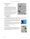
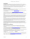
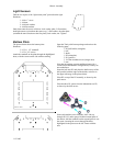
Bend the leads of the voltage regulator half-way through the fat part, near the b
of the IC, as shown in the picture on the right. This will align the mounting hole
over the hole in the PCB and the IC should lie flat when soldered in. (Board
location is shown in the picture in the next section.)
ody
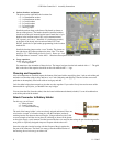
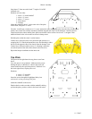
Switch and resonator
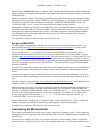
In this step you will install:
1 - switch
1 - ZTT-16.0 resonator
Install in the locations identified in the picture on the right (which shows the
lower right corner for the board). Orientation is not important for the switch or
resonator. The resonator is optional. The ATmega16 has an internal 1, 2, 4, or 8
MHz oscillator. In addition, it can operate with an external source of up to
16MHz, which this resonator provides.
11-3-2005 7


